Device and method for controlling limited slip differential

a technology of limited slip differential and control device, which is applied in the direction of brake system, instruments, transportation and packaging, etc., can solve the problem of reducing the traveling stability on a low road, and achieve the effect of increasing the thermal load

Active Publication Date: 2016-02-11
JTEKT CORP
View PDF6 Cites 15 Cited by
  • Summary
  • Abstract
  • Description
  • Claims
  • Application Information

AI Technical Summary

Benefits of technology

[0011]It is an object of the present invention to provide a control device for a limited slip differential which can suppress an increase in thermal load of the limited slip differential that limits a differential operation of front and rear wheels in a four-wheel-drive vehicle having mounted thereon a vehicle behavior control device that controls behavior of the vehicle by controlling a braking force, and a control method for controlling the limited slip differential.

Problems solved by technology

In such a case, even if differential rotation between the front and rear wheels increases due to slipping of the main driving wheels, the drive state cannot be switched to the four-wheel-drive state, which reduces traveling stability on a low μ road.

Method used


Image

  • Device and method for controlling limited slip differential
  • Device and method for controlling limited slip differential
  • Device and method for controlling limited slip differential

Examples


first embodiment

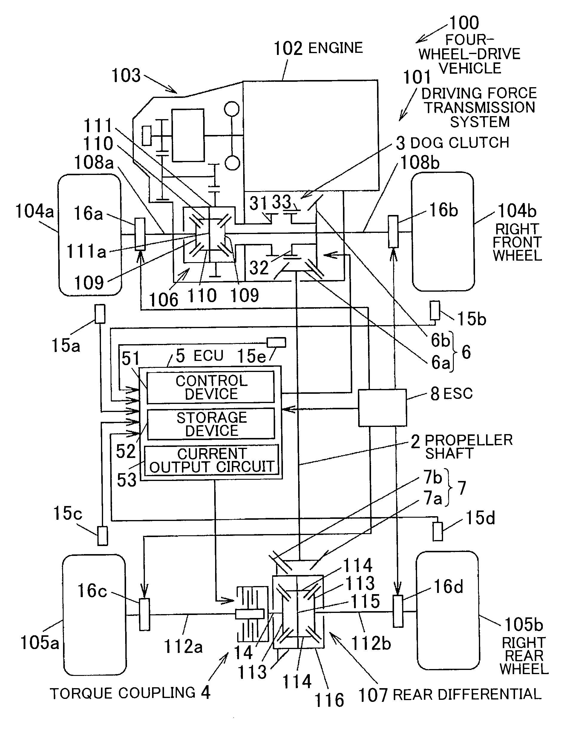
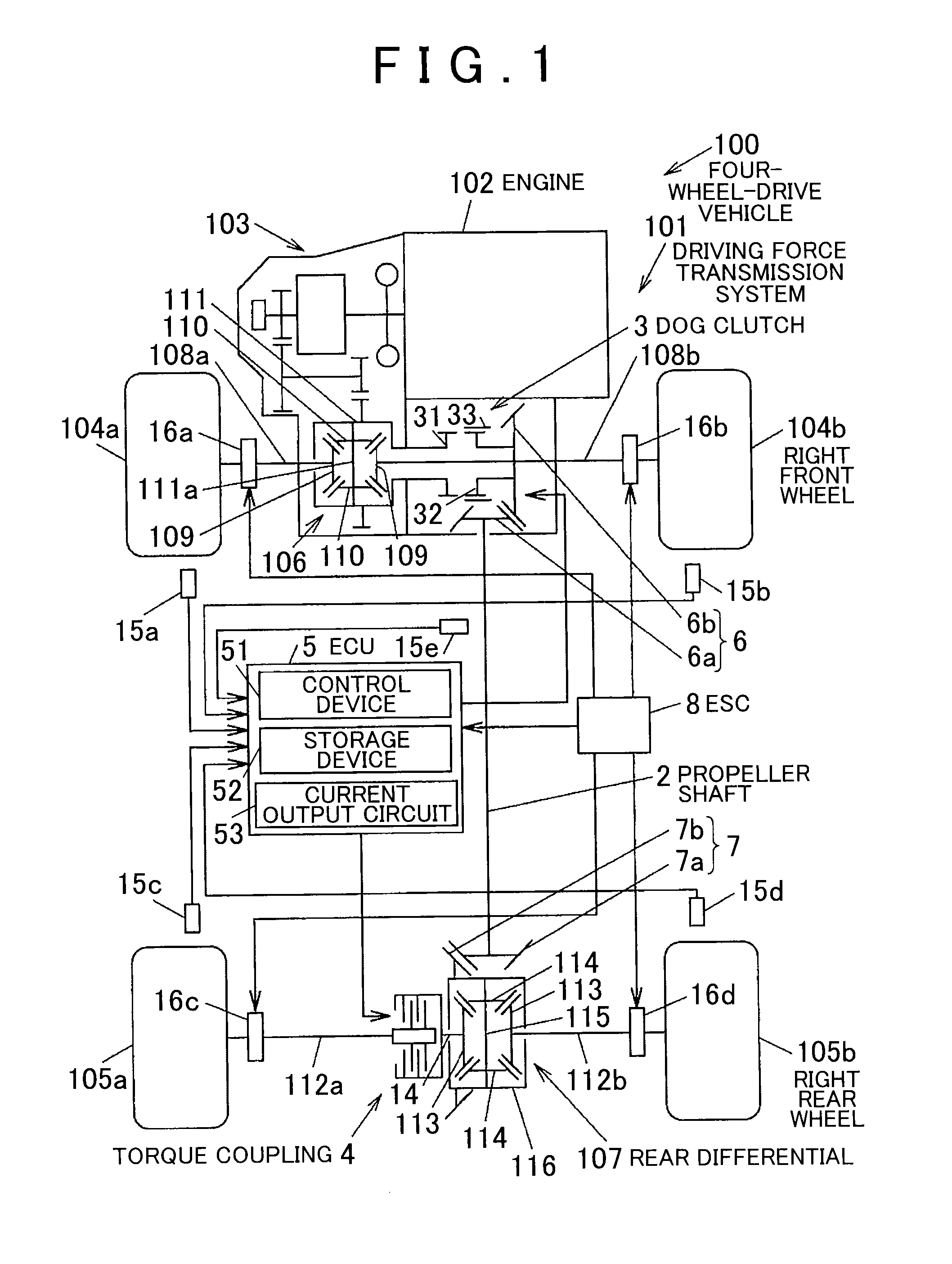
[0022]the present invention will be described with reference to FIG. 1 or 4. FIG. 1 is a diagram schematically showing an example of the configuration of a four-wheel-drive vehicle having mounted thereon a control device for a limited slip differential according to the embodiment of the present invention.

[0023]As shown in FIG. 1, a four-wheel-drive vehicle 100 includes an engine 102, right and left front wheels 104b, 104a, and right and left rear wheels 105b, 105a. The engine 102 is a driving source that generates torque for traveling. The front wheels 104b, 104a are a pair of right and left main drive wheels to which the driving force of the engine 102 is constantly transmitted. The rear wheels 105b, 105a are a pair of right and left auxiliary drive wheels to which the driving force of the engine 102 is transmitted according to the traveling state.

[0024]The four-wheel-drive vehicle 100 can switch between a four-wheel-drive state and a two-wheel-drive state. In the four-wheel-drive ...

second embodiment

[0107]The second embodiment is described with respect to the case where a correction to reduce the target torque T is made in two steps according to the thermal load HE. However, the correction to reduce the target torque T may be made in three or more steps. Alternatively, the correction to reduce the target torque T may be continuously steplessly limited.


PUM


Abstract

In a control device for a limited slip differential that limits a differential operation of front and rear wheels of a four-wheel-drive vehicle having mounted thereon a vehicle behavior control device that controls a braking force, an ECU that controls a torque coupling as the limited slip differential includes: a differential limiting force calculating device that calculates target torque of the torque coupling based on a vehicle traveling state; a differential limiting force correcting device that makes a correction to reduce the target torque based on a command from the vehicle behavior control device; and a thermal load calculating device that calculates a thermal load of the torque coupling. The differential limiting force correcting device limits the correction of the target torque based on the command from the vehicle behavior control device, when the thermal load of the torque coupling is equal to or larger than a predetermined value.

Description

INCORPORATION BY REFERENCE[0001]The disclosure of Japanese Patent Application No. 2014-161238 filed on Aug. 7, 2014 including the specification, drawings and abstract, is incorporated herein by reference in its entirety.BACKGROUND OF THE INVENTION[0002]1. Field of the Invention[0003]The present invention relates to devices and methods for controlling a limited slip differential capable of limiting the differential operation of front and rear wheels of a four-wheel-drive vehicle.[0004]2. Description of the Related Art[0005]Conventionally, four-wheel-drive vehicles are known in the art which include a limited slip differential capable of limiting the differential operation of front and rear wheels of the four-wheel-drive vehicle and a vehicle behavior control device that controls behavior of the vehicle by applying a braking force.[0006]For example, a four-wheel-drive vehicle described in paragraph [0073] of Japanese Patent Application Publication No. 2003-231428 (JP 2003-231428 A) in...

Claims


Application Information

Patent Timeline
Patent Type & Authority Applications(United States)
IPC IPC(8): B60W10/119B60K23/04B60T8/175B60W10/184B60W40/12
CPCB60W10/119B60T8/175B60K23/04B60W10/184B60W2520/263B60W2300/18B60W2400/00B60W2510/12B60W2510/18B60W40/12B60W10/14B60W10/182B60W30/02B60W2710/182B60W2710/12B60W2520/28B60W2540/10B60T2201/14B60K23/0808B60W10/16B60W30/186B60W2540/12B60W2510/0291B60W2510/0604B60W10/02B60W2710/125
Inventor KATO, TOMOAKI
Owner JTEKT CORP
Why Eureka
Try Eureka