Supercharge Your Innovation With Domain-Expert AI Agents!

Mechanical pipe fitting

a technology of mechanical fittings and fittings, which is applied in the direction of pipe joints, pipeline expansion compensation, screw threaded joints, etc., can solve the problems of increasing the cost of mechanical fittings, so as to achieve the effect of preventing relative rotation

Inactive Publication Date: 2016-02-11
SHURJOINT METALS INC
View PDF16 Cites 8 Cited by
  • Summary
  • Abstract
  • Description
  • Claims
  • Application Information

AI Technical Summary

Benefits of technology

This patent describes a mechanical fitting for joining multiple pipes together. The fitting includes a housing with an internal fluid flow passage connected to the pipes. An interchangeable insert with compatible materials and designs can be used to reduce production and stocking costs. The fitting can also have branch connections for more complex pipe networks. The design allows for efficient use of materials and reduces the number of parts needed. The technical effects of the patent include improved cost efficiency and flexibility in design options for mechanical fittings.

Problems solved by technology

In addition, these different materials can have different physical strengths and costs.
Thus, a bronze mechanical tee can be more expensive and weaker than a comparable ductile iron mechanical tee.
Moreover, a stainless steel mechanical tee would be even more expensive than an equivalent bronze or ductile version.

Method used


Image

  • Mechanical pipe fitting
  • Mechanical pipe fitting
  • Mechanical pipe fitting

Examples


Embodiment Construction

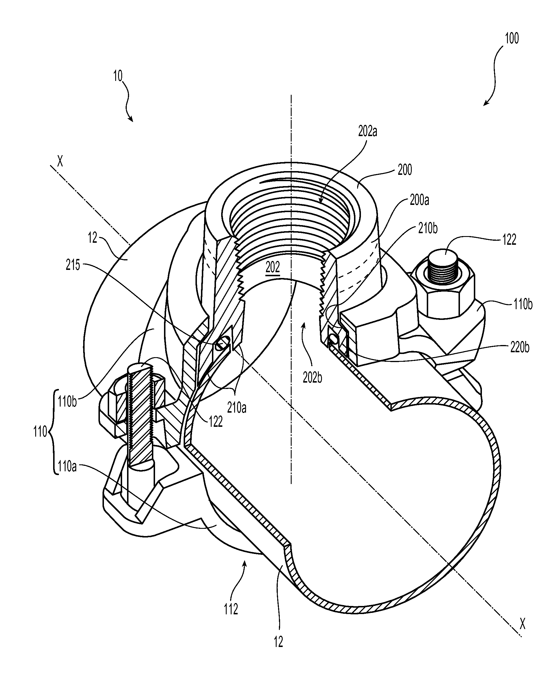
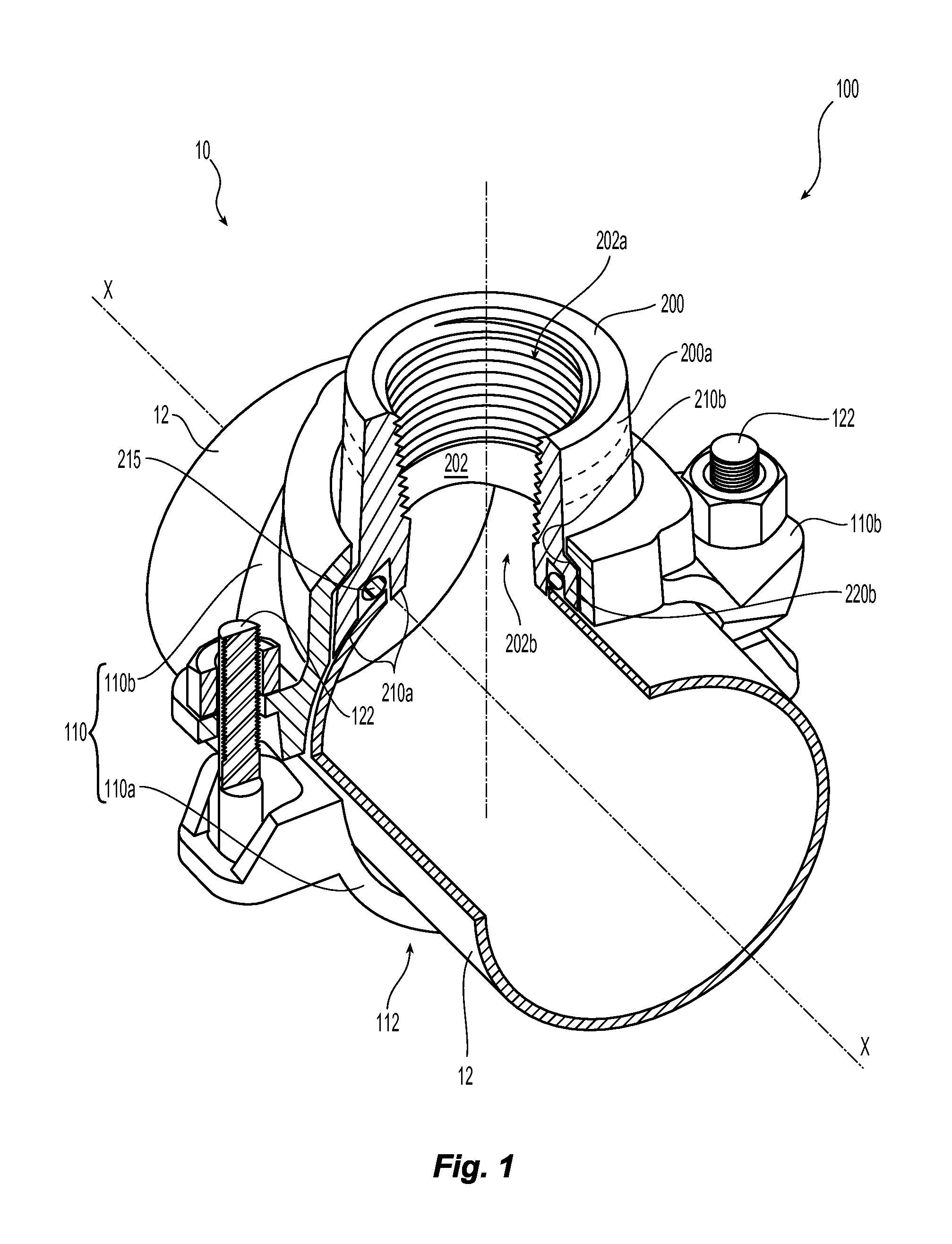
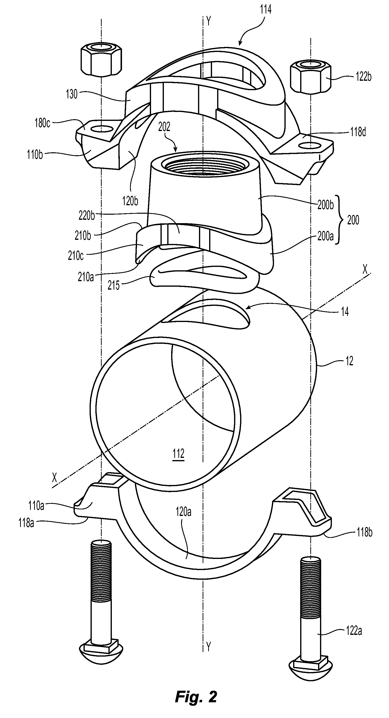
[0026]Shown in FIGS. 1 and 2 is a branch connection 10 formed with a preferred embodiment of a mechanical fitting 100. The preferred mechanical fitting 100 includes a housing 110 disposed about the pipe segment 12 with an insert 200 disposed in and extending from the housing 110 to provide the subject branch connection to a pipe housed in the housing 110. The housing 110 preferably includes a first or lower housing segment 110a and a second or upper housing segment 110b which are coupled together, preferably by a pair of mechanical fasteners 122 to define an interior space 112 defining a central axis X-X in which the pipe segment 12 is axially housed. Alternatively, instead of the lower housing segment 110a and the pair of mechanical fasteners 122, a bolt in the shape of a U could be utilized. Moreover, a suitable arrangement could be employed to secure the upper housing segment 110b to the pipe segment 12, such as, a strap or a clamp.

[0027]The preferably tubular insert 200 has a ba...


PUM


Abstract

Devices and methods for coupling fluid conveying piping (12) in an arrangement to provide a one or more branch connections. A mechanical fitting includes a lower housing (110a) and an upper housing (110b) coupled to one another to define an interior space (112) for housing a tubular pipe segment (12). At least one insert (200) for insertion in one of the upper or lower housing includes a tubular body (200b) that defines a fluid flow passageway (202) and a base (200a) that engages an opening (14) in the pipe segment (12). The base and housings are configured to engage one another to prevent rotation of the insert (200) with respect to the housing (110).

Description

PRIORITY DATA[0001]This application claims the benefit of U.S. Provisional Application No. 61 / 802,135, filed Mar. 15, 2013, and U.S. Provisional Application No. 61 / 819,420, filed May 3, 2013, each of which application is incorporated herein by reference in its entirety.TECHNICAL FIELD[0002]This invention relates generally to pipe fittings and more specifically devices and methods for coupling fluid conveying piping in an arrangement providing one or more branch connections.BACKGROUND OF THE INVENTION[0003]Mechanical tees provide a fast and easy mid-point branch outlet which is perpendicular to a main pipe in a piping system. Traditional mechanical tees are comprised of an upper and lower housing, an elastomeric gasket and a pair of bolts and nuts. To install a mechanical tee a prescribed sized hole is cut on the centerline of the main pipe. The upper housing and gasket are positioned around the hole. The lower portion of the housing is then positioned on the underside of the pipe op...

Claims


Application Information

Patent Timeline
Patent Type & Authority Applications(United States)
IPC IPC(8): F16L41/02F16L15/08F16L41/14
CPCF16L41/021F16L41/14F16L15/08F16L41/12
Inventor CHENG-SHENG, HSULIPPKA, SANDRA M.DUNCHAK, KRISTY M.
Owner SHURJOINT METALS INC
Features
  • R&D
  • Intellectual Property
  • Life Sciences
  • Materials
  • Tech Scout
  • Unparalleled Data Quality
  • Higher Quality Content
  • 60% Fewer Hallucinations
Learn More