Radar apparatus and object sensing method

a technology of object sensing and apparatus, applied in the field of radar apparatus and object sensing method, can solve the problems of difficult to detect a small reflected power object, and the difficulty of the related art in detecting the human separately from the vehicl

Active Publication Date: 2016-02-11
PANASONIC CORP
View PDF1 Cites 69 Cited by
  • Summary
  • Abstract
  • Description
  • Claims
  • Application Information

AI Technical Summary

Benefits of technology

[0008]One non-limiting and exemplary embodiment provides a radar apparatus and an object sensing method that can more reliably sense each of a plurality of objects.
[0010]According to the present disclosure, it is possible to more reliably sense each of a plurality of objects.

Problems solved by technology

However, in the technologies disclosed in Patent Documents 1 and 2 (hereinafter referred to as “related art”), It is difficult to detect an object whose reflected power is small, and is located in the direction in which another object is also located.
Thus, for example, when a human, which is an object having a small reflected power, is located in the vicinity of a vehicle, which is an object having a large reflected power, it is difficult for the related art to detect the human separately from the vehicle.

Method used


Image

  • Radar apparatus and object sensing method
  • Radar apparatus and object sensing method
  • Radar apparatus and object sensing method

Examples


Embodiment Construction

[0039]One embodiment of the present disclosure will be described below in detail with reference to the accompanying drawings.

[0040]First, a description will be given of an overview of object sensing in the present embodiment.

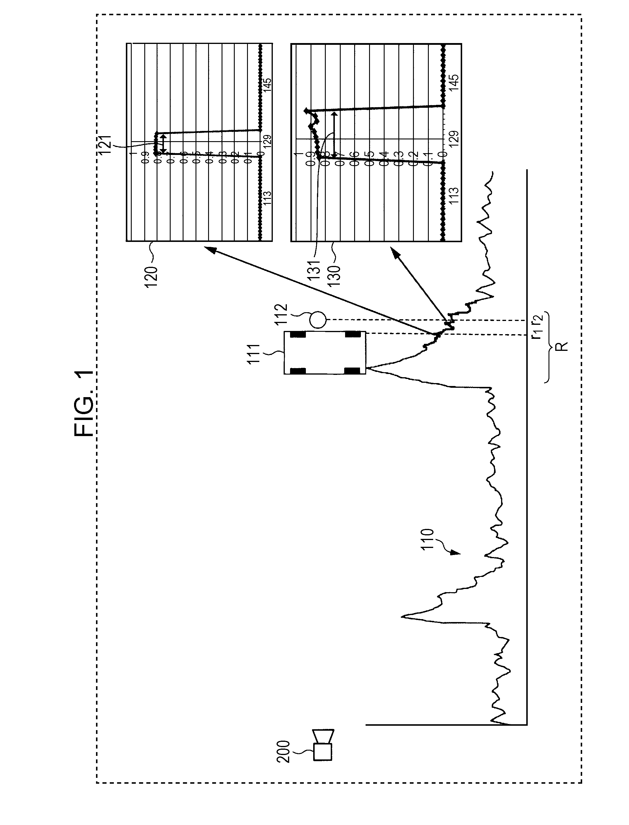
[0041]FIG. 1 is a diagram illustrating an overview of object sensing in the present embodiment.

[0042]In FIG. 1, a delay profile 110 is one example of a delay profile when a pedestrian 112 is beside a vehicle 111. In the delay profile 110, the horizontal axis indicates a distance from a radar apparatus, and the vertical axis indicates the power of an echo signal (a reception signal) received by the radar apparatus (this power is hereinafter simply referred to as “power”).

[0043]In the following description, the distance from a radar apparatus 200 is represented using a range bin, which is a unit obtained by dividing a distance on which the radar apparatus performs sensing. The vehicle 111 is located in a first range bin r1, and the pedestrian 112 is located at a s...


PUM


Abstract

A radar apparatus includes an antenna that receives echo signals, each of the echo signals being a radar signal reflected by one or more objects; a Doppler-frequency acquirer that acquires Doppler frequencies at each range bin from the received echo signals; a direction correlation power-value calculator that calculates direction correlation power values for respective combinations of the Doppler frequencies and at least one of a distance to the one or more objects and an arrival direction of the echo signals, each direction correlation power value indicating a strength of a corresponding echo signal; and a normalized direction correlation-value calculator that calculates, for the respective combinations, normalized direction correlation values, each normalized direction correlation value indicating a probability of the arrival direction of the corresponding echo signal.

Description

BACKGROUND[0001]1. Technical Field[0002]The present disclosure relates to a radar apparatus and an object sensing method.[0003]2. Description of the Related Art[0004]Technologies for sensing an object (target) by using a radar apparatus are disclosed in, for example, Japanese Unexamined Patent Application Publication No. 60-122381 (hereinafter referred to as “Patent Document 1”) and Japanese Unexamined Patent Application Publication No. 2011-180030 (hereinafter referred to as “Patent Document 2”).[0005]In the technology disclosed in Patent Document 1, radar reception waves (reception signals) including reflected waves from an object and ground clutter, which refers to reflected waves from the ground surface, are sampled for each range bin, and Doppler components of the reception signals are determined for each range bin. The range bin is a unit of processing for a distance on which searching is to be performed. In the technology disclosed in Patent Document 1, the magnitude of chang...

Claims


Application Information

Patent Timeline
Patent Type & Authority Applications(United States)
IPC IPC(8): G01S13/42G01S7/282G01S7/285G01S13/931
CPCG01S13/42G01S7/285G01S7/282G01S7/2927G01S7/4026G01S13/28G01S13/284G01S13/522G01S13/584G01S13/726G01S13/931G01S2013/0245
Inventor CAO, YUNYUNNISHIMURA, HIROFUMIHAMADA, ASAKOKISHIGAMI, TAKAAKI
Owner PANASONIC CORP
Why Eureka
Try Eureka