Drive circuit for a permanent magnet motor
- Summary
- Abstract
- Description
- Claims
- Application Information
AI Technical Summary
Benefits of technology
Problems solved by technology
Method used
Image
Examples
Embodiment Construction
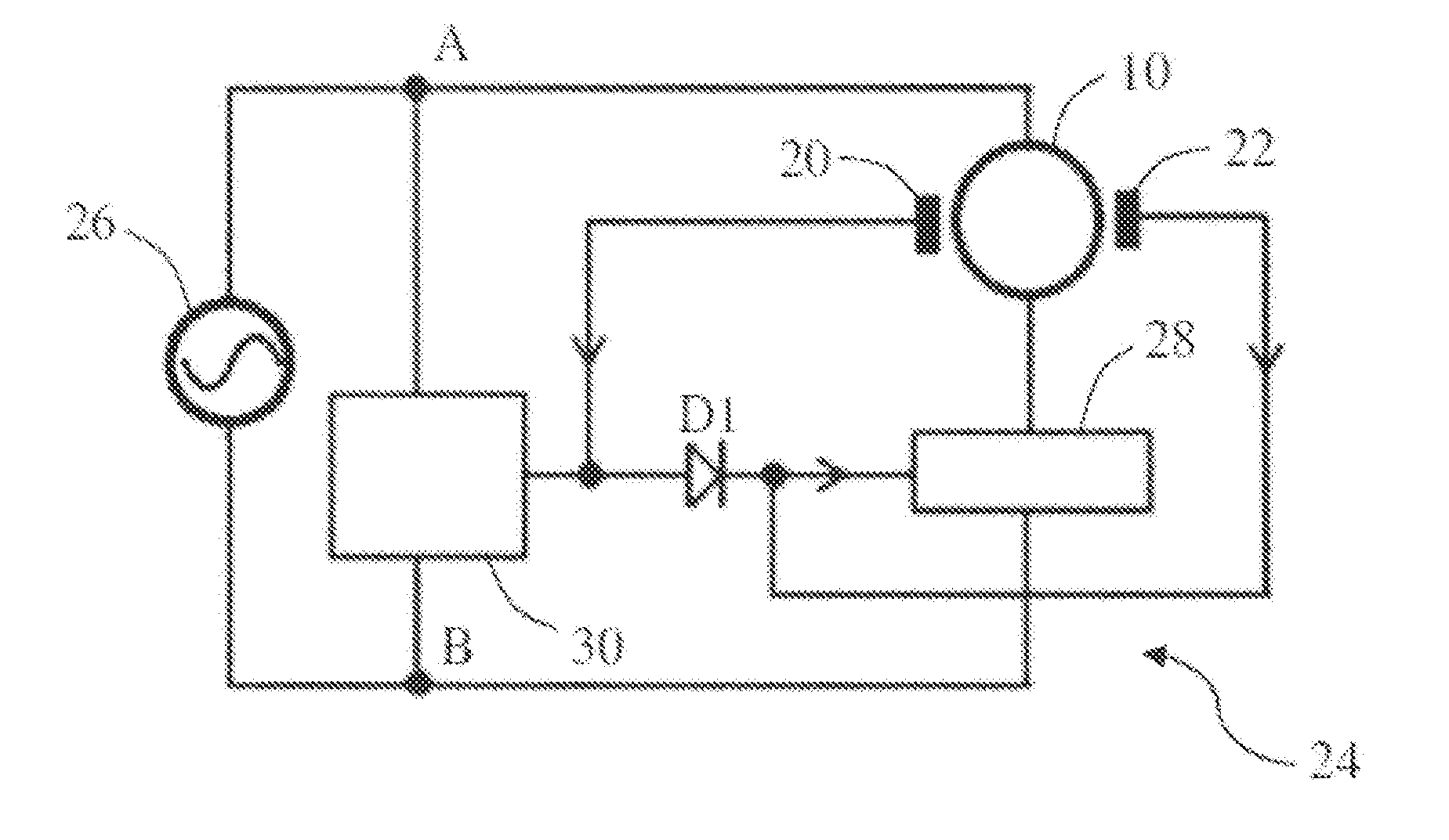
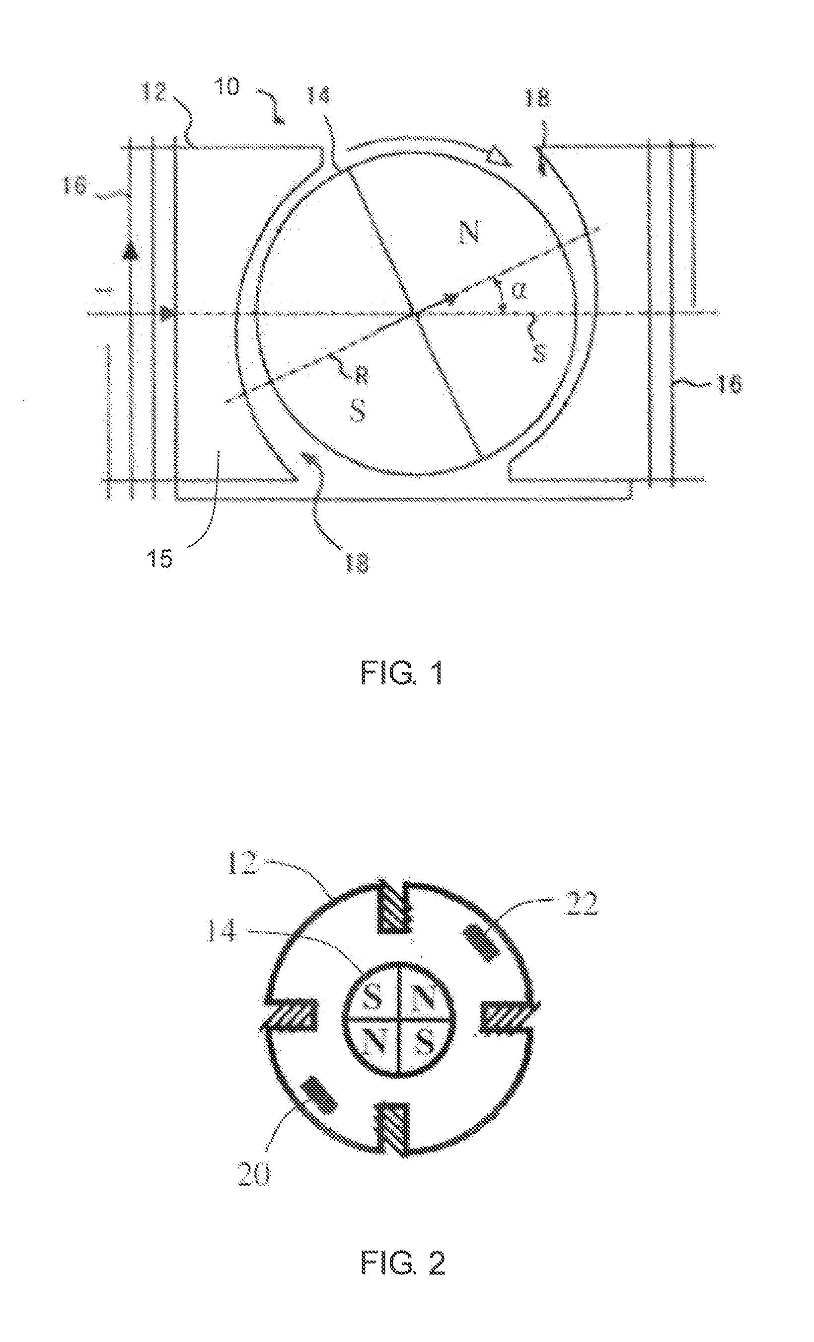
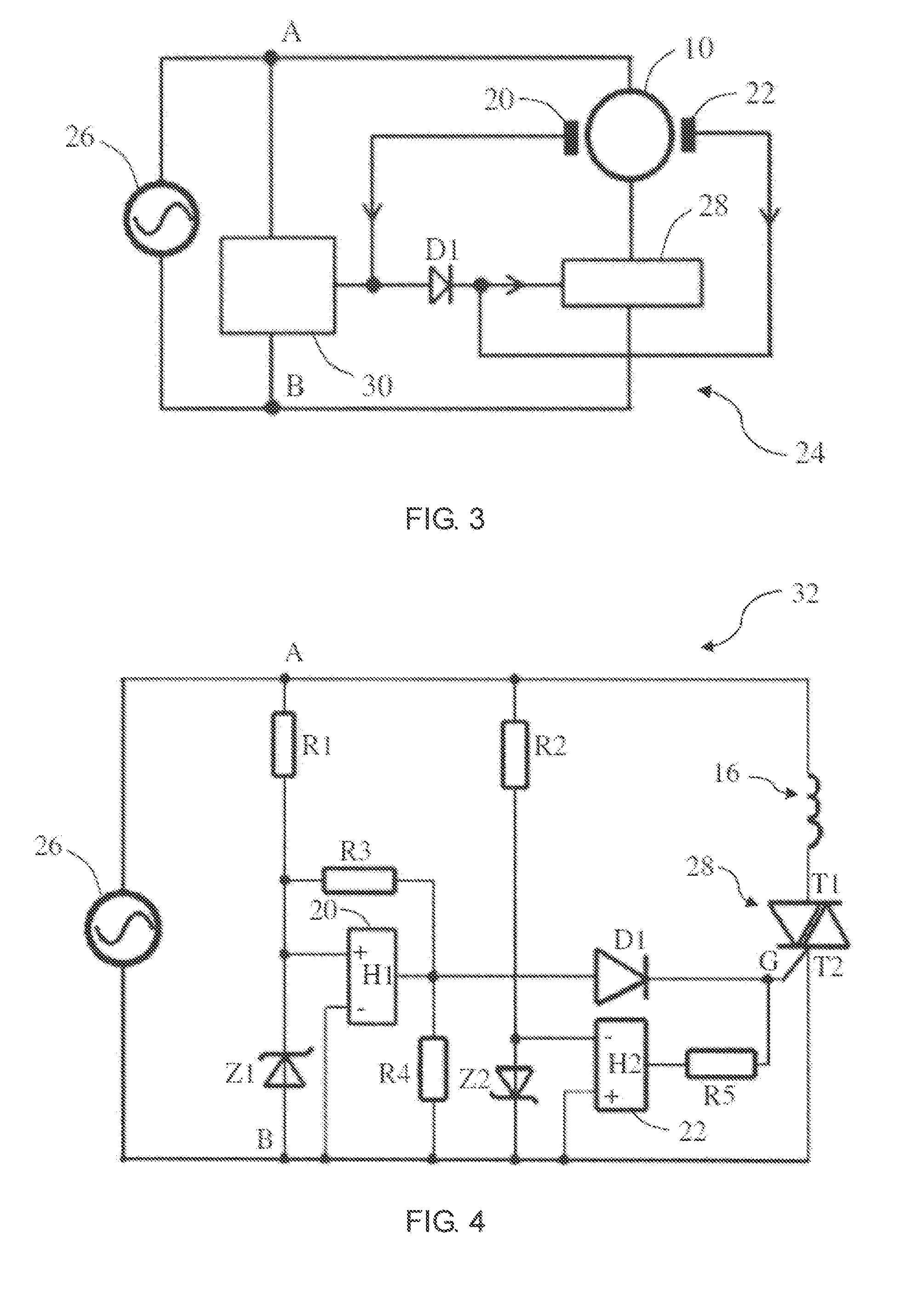
[0026]FIG. 1 is a schematic diagram of a synchronous motor in accordance with an embodiment of the present invention. The synchronous motor 10 comprises a stator 12, and a permanent magnet rotor 14 rotatably disposed between the magnetic poles of the stator 12. The stator 12 has a stator core 15 and a stator winding 16 wound on the stator core. The rotor 14 includes at least one permanent magnet forming at least one pair of permanent magnetic poles with opposite polarities. The rotor 14 operates at a constant rotational speed of 60 f / p during a steady state phase of operate when the stator winding 16 and an AC power supply are connected in series, where f is a frequency of the AC power supply and p is the number of pole pairs of the rotor.
[0027]A non-uniform air gap 18 is formed between the magnetic poles of the stator 12 and the magnetic poles of the rotor 14, thus enabling the polar axis R of the rotor 14 to be offset by an angle α with respect to the central axis S of the stator ...
PUM
 Abstract
Description
Claims
Application Information
 - R&D
- Intellectual Property
- Life Sciences
- Materials
- Tech Scout
- Unparalleled Data Quality
- Higher Quality Content
- 60% Fewer Hallucinations
Browse by: Latest US Patents, China's latest patents, Technical Efficacy Thesaurus, Application Domain, Technology Topic, Popular Technical Reports.
© 2025 PatSnap. All rights reserved.Legal|Privacy policy|Modern Slavery Act Transparency Statement|Sitemap|About US| Contact US: help@patsnap.com


