Enclosure access apparatus and method

Inactive Publication Date: 2016-02-18
HUYNH NAM DUC
View PDF26 Cites 32 Cited by
  • Summary
  • Abstract
  • Description
  • Claims
  • Application Information

AI Technical Summary

Benefits of technology

[0004]The following summary may introduce the reader to the more detailed discussion

Problems solved by technology

The opening and closing of enclosures spaces may be diffi

Method used


Image

  • Enclosure access apparatus and method
  • Enclosure access apparatus and method
  • Enclosure access apparatus and method

Examples


first embodiment

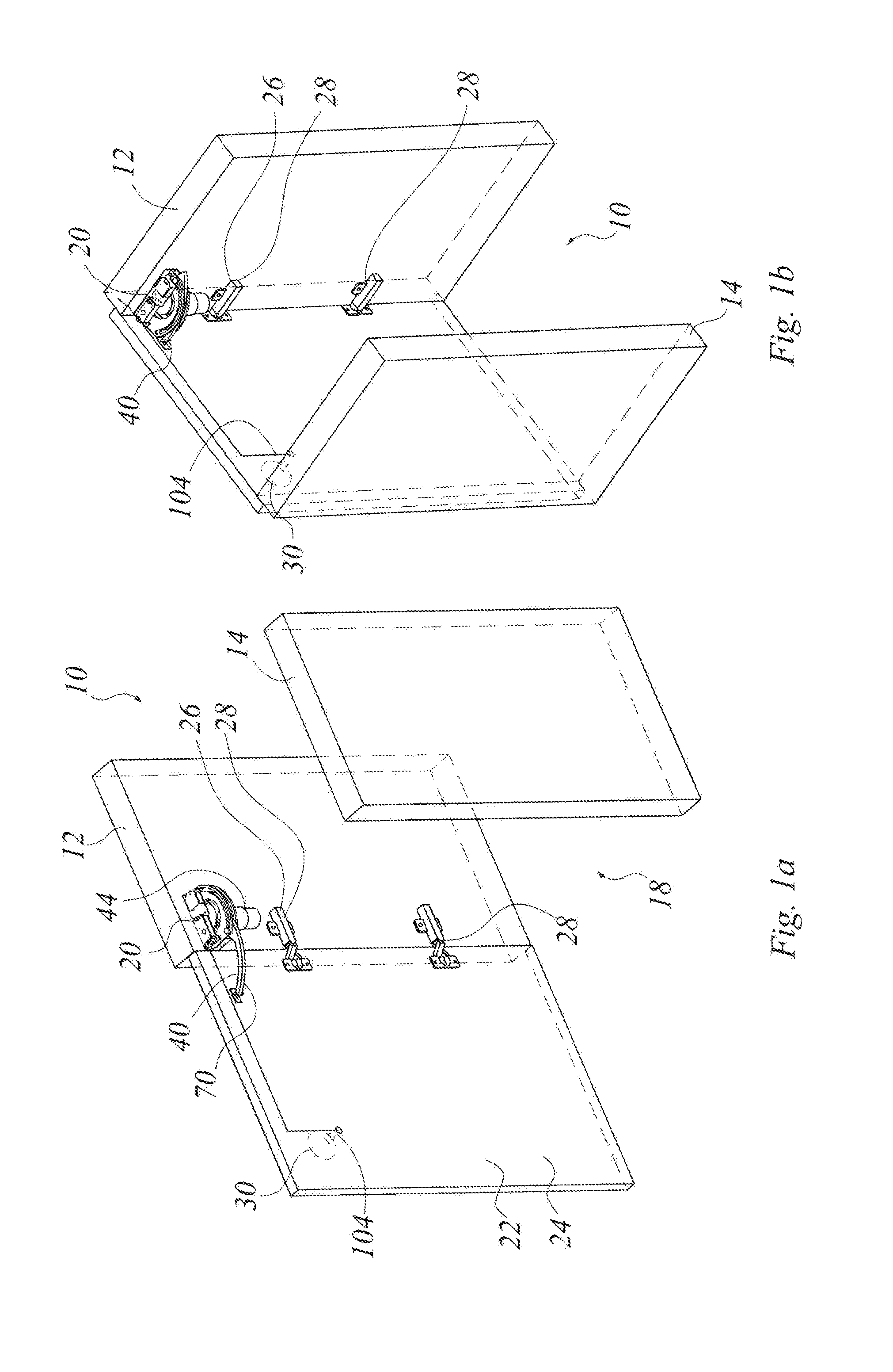
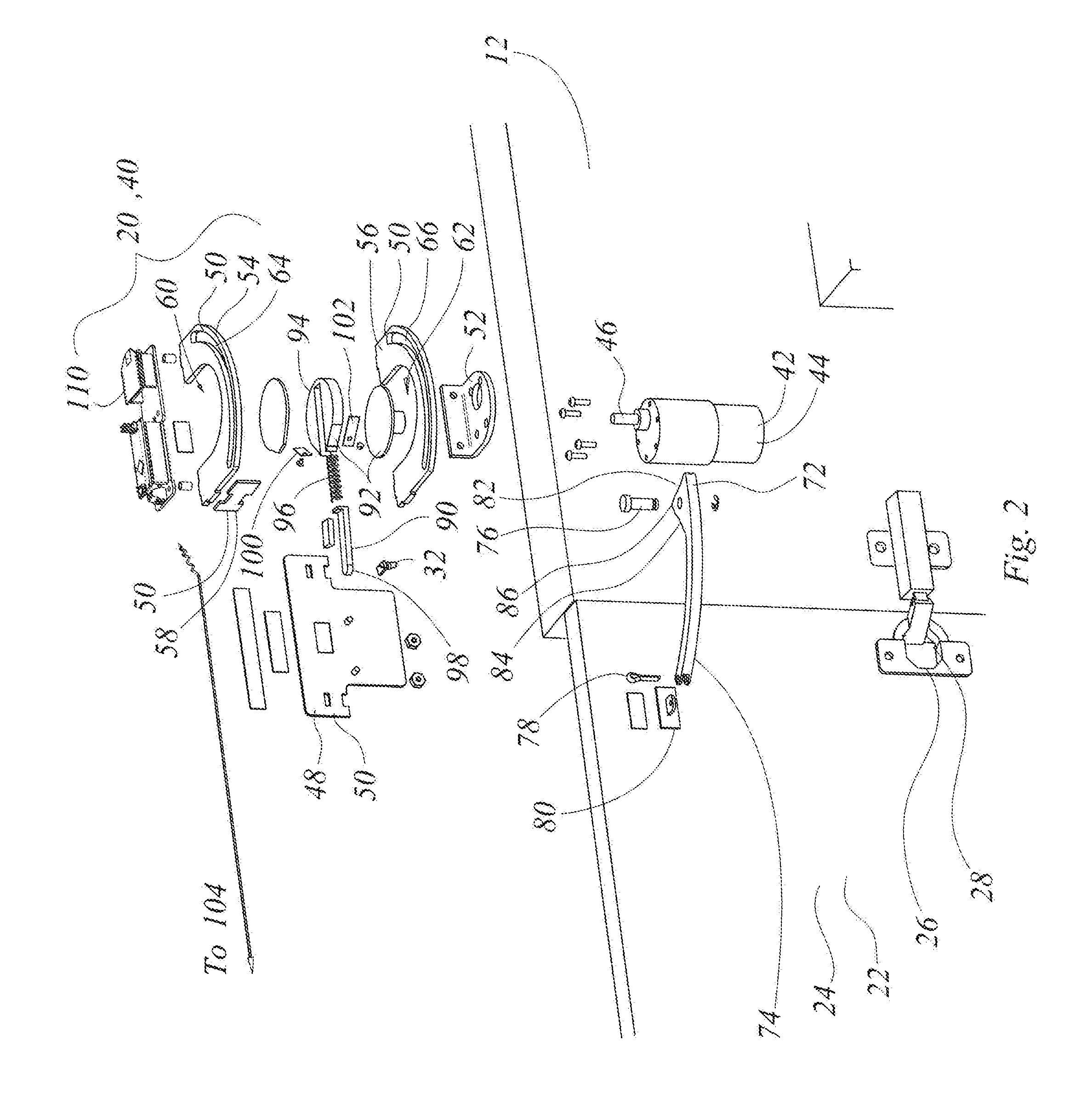
[0043]In this description, without limiting the generality of the narrative, there are two disclosed embodiments. In a first embodiment, such as shown in FIGS. 1a to 4b there is a an access governing apparatus 20 for a door assembly 22 that moves arcuately, that is, the motion of the door is not merely of linear translation but may include, or may be entirely, an angular motion. The motion is a reciprocating motion, and, in the embodiment shown, is an angularly reciprocating motion about hinges. In the embodiment of FIGS. 5a to 9 there is an access opening operation assembly that has a linear motion embodiment. That is, in the embodiment of FIG. 9 the apparatus may pertain to a drawer, or to a linearly sliding access door. These devices are intended to open or close the door or drawer, as may be, automatically by actuators.

[0044]In FIG. 1, the mechanism is used to open swing doors which may be, for example, kitchen cabinet doors. In FIG. 2, the sliding mechanism may be used for kitc...

second embodiment

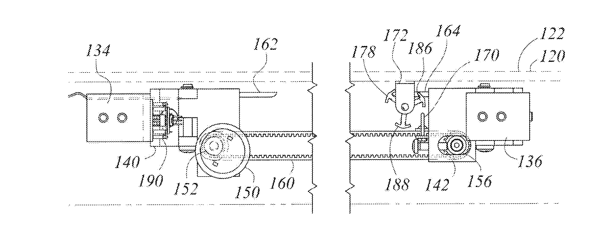
[0083]In the second embodiment, the drive transmission is set underneath the drawer. The rotatable anchor mechanism is permanently attached to drawer with the rotatable three-armed members. The hook is mounted on the timing belt drive. The timing belt is driven by the 6 / 12V motor 150. When the apparatus receives a command to open, motor 150 drives the hook forward, encountering and snagging the anchor on its way to pull the drawer open. At the destination, the flip gear (located beside the anchor on the keyed shaft in the illustrations) will hit a stop bar, be it 162 or 164. The stop bar turns the flip gear to make the hook release the anchor, and then stop. Similarly, when the motor turns opposite direction, it brings the drawer in toward the closed position.

[0084]The various embodiments may include one or more of the automatic cabinet openers that have individual mechanism as showing in the first embodiment of FIGS. 1a-4b in which the driven link reciprocates along the same path i...


PUM


Abstract

Automatic Kitchen Cabinet openers may frequently include two types of mechanisms. One type of mechanism is designed for a swinging door, such as a cupboard door. Another type is designed for sliding drawers. For a swinging door mechanism, a rotational motion is generated by a bi-directional servo motor to open or close, or open and close, the door. On a sliding mechanism, rotational motion of a geared motor may be converted to translational motion to slide the drawer in or out. These motors are controlled by a microcontroller as one system or individual unit with IR motion sensor integration or remotely via Wi-Fi or Bluetooth or voice control. In some embodiments the mechanisms may be operated by 6V or 12V DC battery adapter.

Description

[0001]This application claims the benefit of the priority of U.S. provisional patent application U.S. Ser. No. 61 / 770,296 filed Feb. 27, 2013, the specification and drawings of which are hereby incorporated herein by reference.FIELD OF INVENTION[0002]This apparatus and method herein pertain to enclosures and access to enclosures.BACKGROUND OF THE INVENTION[0003]The opening and closing of enclosures spaces may be difficult for persons of limited mobility or physical strength. In such circumstances, or in circumstances where the person wishing access is inhibited from opening an enclosure, or is only able gently to touch the enclosure rather than to apply force to control opening and closing, it may be helpful to have a more automated approach.SUMMARY OF INVENTION[0004]The following summary may introduce the reader to the more detailed discussion to follow. The summary is not intended to, and does not, limit or define the claims.[0005]In an aspect of the invention there is an enclosur...

Claims


Application Information

Patent Timeline
IPC IPC(8): E05F15/77A47B88/04E05F11/00E05F13/00E05F15/603E05F15/74
CPCE05F15/77E05F15/603E05F15/74E05F2015/765E05F11/00A47B88/0414E05F2015/763E05F13/00A47B88/457E05Y2600/526E05Y2900/20E05F15/63E05F15/73
Inventor HUYNH, NAM, DUC
Owner HUYNH NAM DUC
Why Eureka
Try Eureka