Downhole Apparatus

Inactive Publication Date: 2016-02-18
WEATHERFORD TECH HLDG LLC
View PDF2 Cites 12 Cited by
  • Summary
  • Abstract
  • Description
  • Claims
  • Application Information

AI Technical Summary

Benefits of technology

[0046]Providing an apparatus according to embodiments of the present invention may permit a sealing contact to be provided and maintained in an axial flow passage having such a restriction, since the seal members may be spaced so that where one seal member is adjacent to the profile portion which may otherwise result in fluid bypass, at least one other of the seal members is positioned adjacent to a portion of the downhole tool which permits a sealing contact to be provided between the apparatus and the downhole tool, thus ensuring that a sealing contact i

Problems solved by technology

However, since many completion string tools extend into or require access to an axial throughbore or flow passage of the string, these tools and associat

Method used


Image

  • Downhole Apparatus
  • Downhole Apparatus
  • Downhole Apparatus

Examples


Example

DETAILED DESCRIPTION OF DRAWINGS

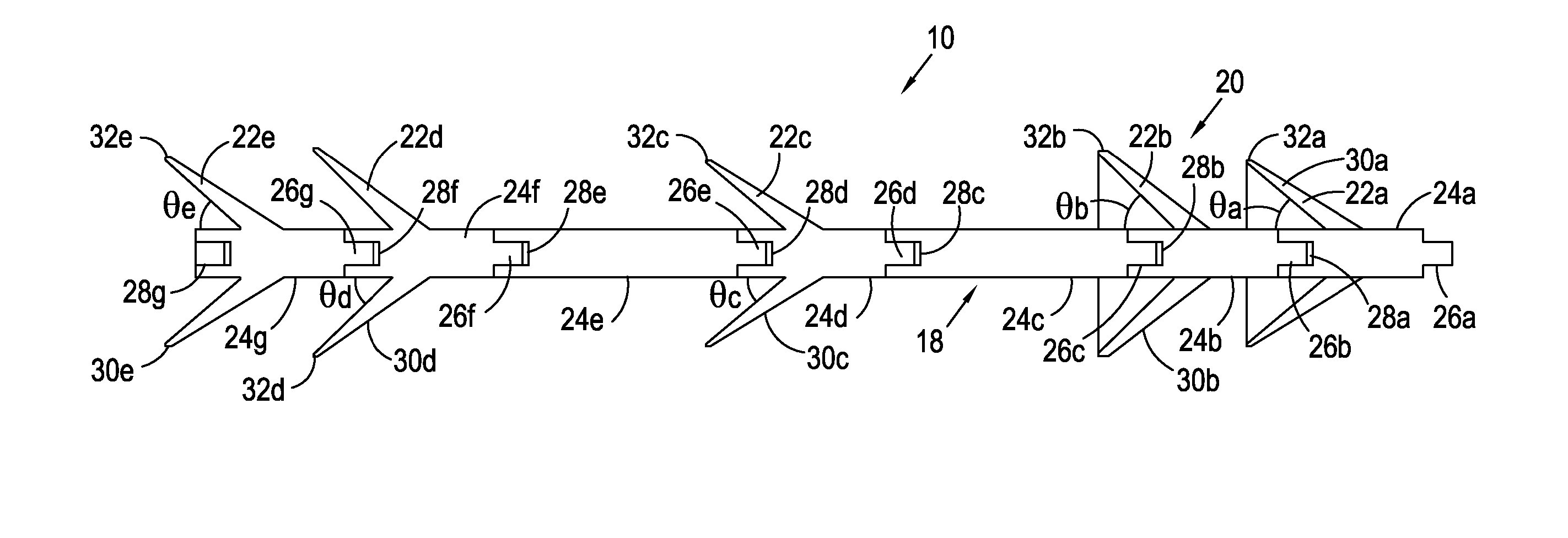
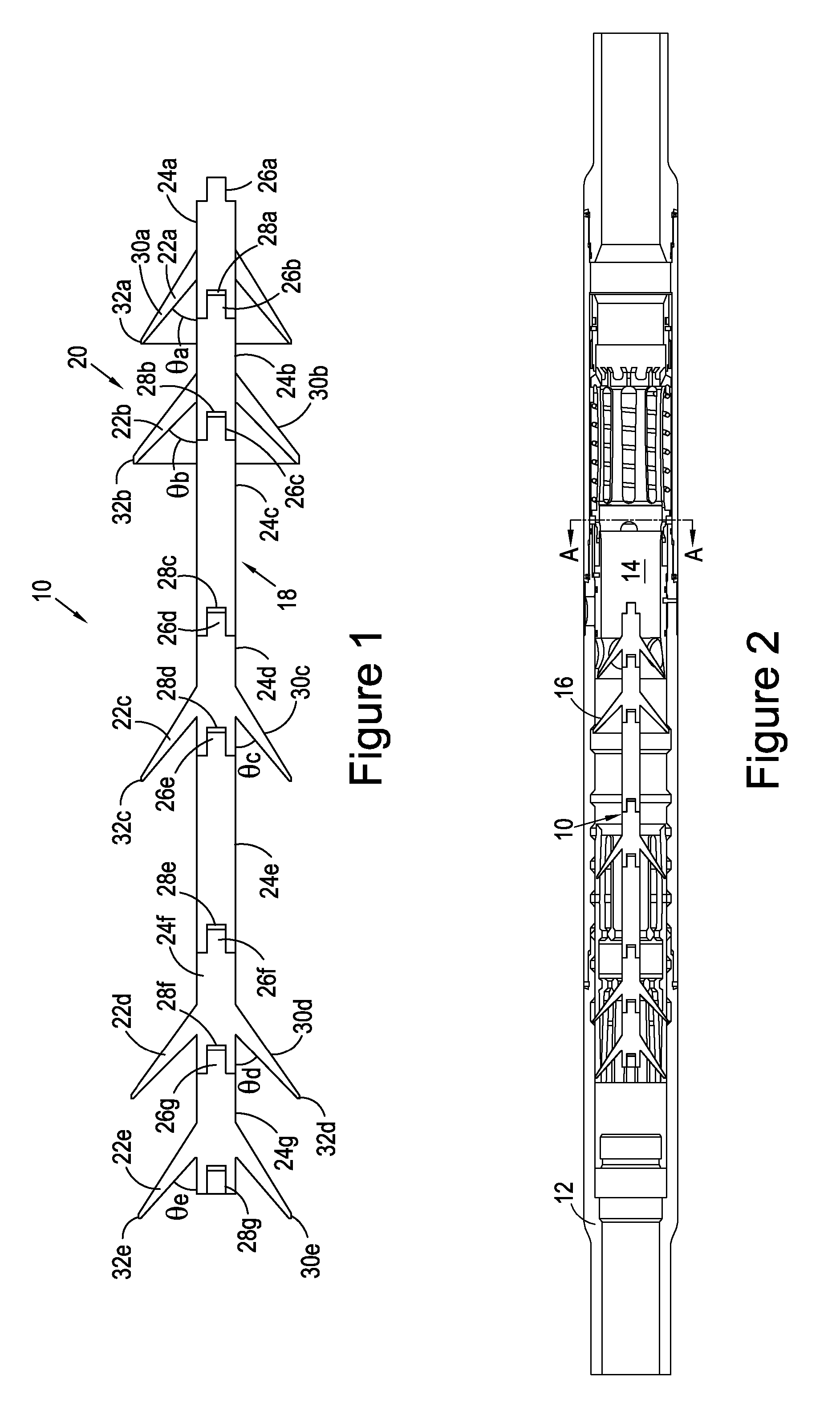
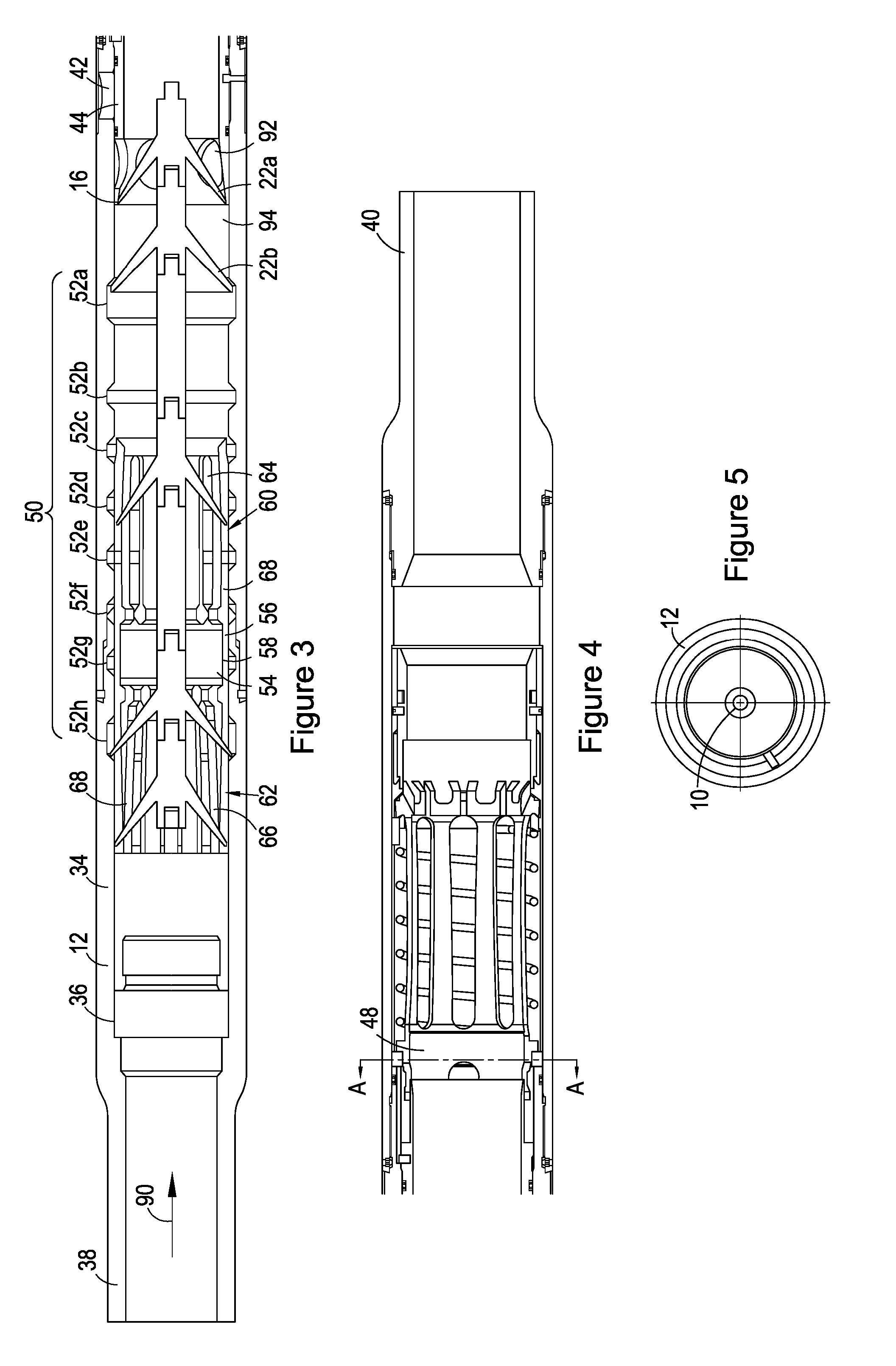
[0111]Referring first to FIGS. 1 and 2, there is shown a downhole cementing apparatus, in the form of a cement dart 10, according to an embodiment of the present invention. In use, the dart 10 may be employed during a downhole cementing operation, the dart 10 being deployable through a downhole tool 12 (FIG. 2) with a volume of cement 14 and configured to provide a varying point of sealing contact 16 between the dart 10 and the downhole tool 12 which permits the cement 14 to be driven through the downhole tool 12.

[0112]As shown in FIG. 1, the dart 10 comprises a body in the form of a mandrel 18 and a sealing arrangement 20 for providing the sealing contact 16. In the illustrated embodiment, the sealing arrangement 20 comprises a plurality of axially spaced seal members 22a, 22b, 22c, 22d, 22e and, in use, the dart 10 is configured so that as the dart 10 is deployed though the downhole tool 12 the point of sealing contact 16 between the dart 10 and the...


PUM


Abstract

A downhole cementing apparatus (10) comprises a body (18) and a sealing arrangement (20) mounted on the body. The cementing apparatus (10) is deployable through a downhole tool (12) with a volume of cement (14). The sealing arrangement (20) is configured to define a varying point of sealing contact axially along the sealing arrangement with an inner surface of a downhole tool (12) as the cementing apparatus (10) is deployed through said tool.

Description

FIELD OF INVENTION[0001]The present invention relates to the transport of a fluid, such as cement, through a downhole tool or assembly.BACKGROUND TO INVENTION[0002]In the oil and gas exploration and production industry, well boreholes are drilled from surface in order to access subsurface hydrocarbon-bearing formations. A tubular string, such as a completion string, may be run into the borehole and the annulus between the outside of the string filled with a fluid, such as cement. Cementing operations may be required at various instances during the life cycle of a well, for example to assist in securing and supporting the string in the borehole during its initial completion, to prevent uncontrolled migration of fluid in the annulus, to provide isolation of one or more formation zone during production, and / or during remedial or workover operations.[0003]Completion strings beneficially provide the ability to perform a number of different operations in the borehole, the various completi...

Claims


Application Information

Patent Timeline
IPC IPC(8): E21B37/02E21B33/13
CPCE21B33/13E21B37/02E21B43/261E21B43/26
Inventor WEBSTER, OLIVERPATTON, DAMIEN GERARD
Owner WEATHERFORD TECH HLDG LLC
Why Eureka
Try Eureka