Method and apparatus to utilize the push-pull power of an upwards flow of wind energy within a structure

a technology of push-pull power and wind energy, which is applied in the direction of lighting and heating apparatus, ventilation systems, heating types, etc., can solve the problems of not fully addressing the specific structural requirements of wind energy structures in detail, and not enough to add noticeable weigh

Inactive Publication Date: 2016-02-18
FEX JR JAMES PATRICK
View PDF5 Cites 20 Cited by
  • Summary
  • Abstract
  • Description
  • Claims
  • Application Information

AI Technical Summary

Problems solved by technology

I will not address the specific structural requirements of wind energy structures in great detail; because I am not trying to claim and / or patent any kind and / or type of new support structure.
Several will be on swivels with tail fins but only a few and not enough to add noticeable weight.

Method used


Image

  • Method and apparatus to utilize the push-pull power of an upwards flow of wind energy within a structure
  • Method and apparatus to utilize the push-pull power of an upwards flow of wind energy within a structure
  • Method and apparatus to utilize the push-pull power of an upwards flow of wind energy within a structure

Examples


Embodiment Construction

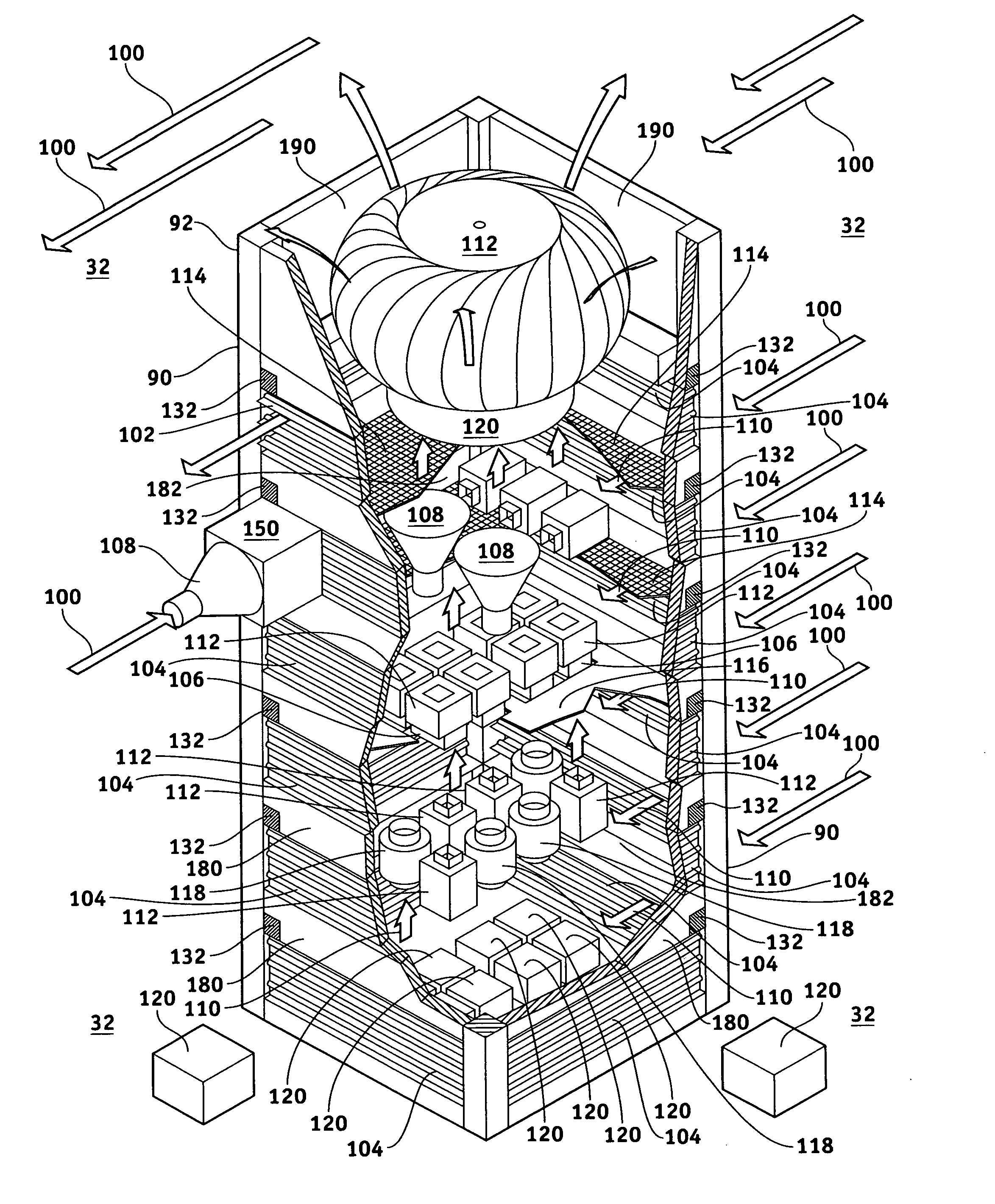
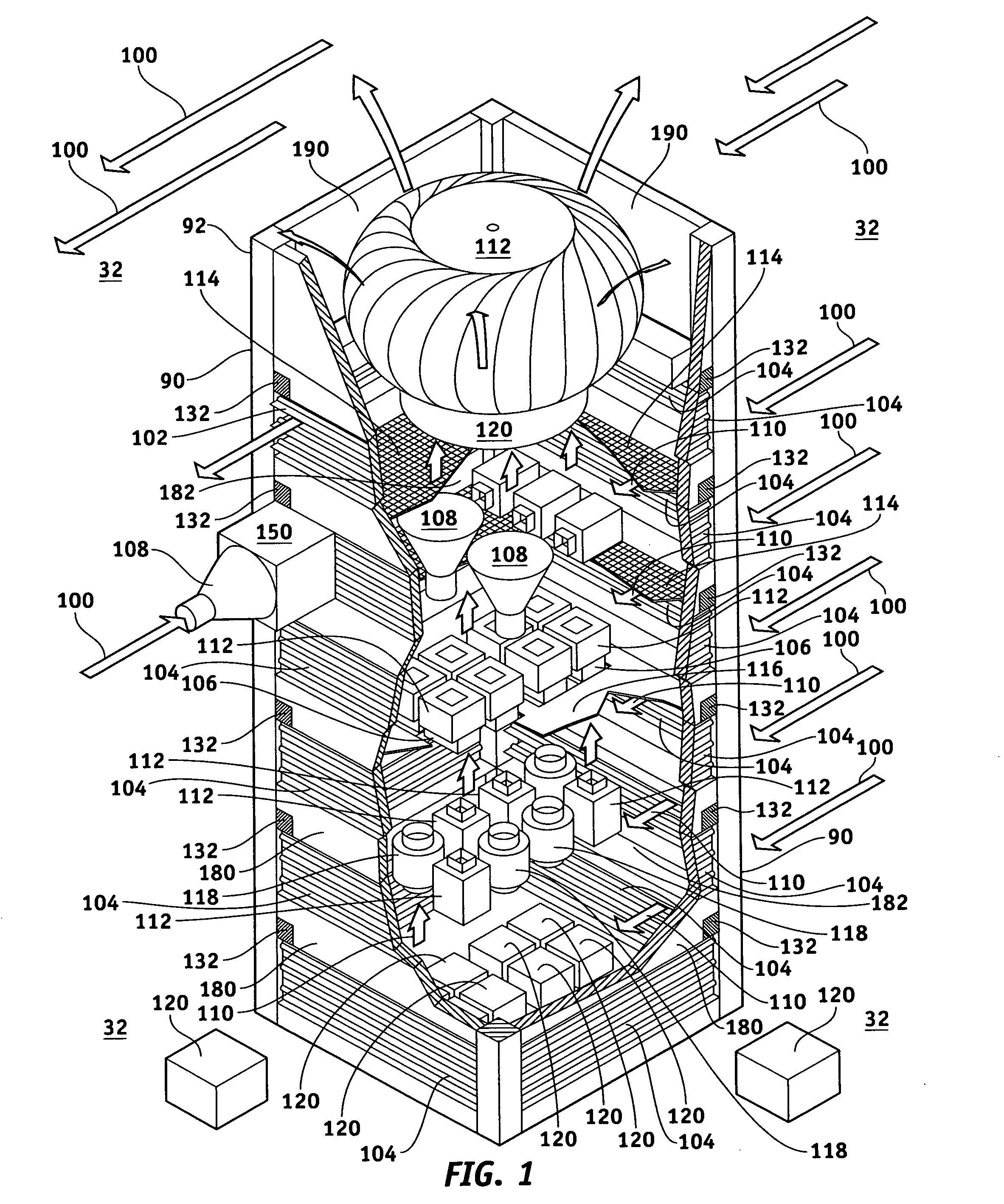
[0260]FIGS. 5-7 Illustrates how to utilize “Bernoulli's Principal” to create the World's first push-pull wind energy structure 90. Involving an apparatus and method for utilizing the power of an upwards flow of wind energy 110 within wind energy structure 90, with one or more open tops 190, one or more structural supports 210 and 212, and one or more external surfaces 180, separating one or more internal areas 182 with one or more floors 202 with one or more rooms 204 with one or more internal surfaces 184, from an outside 32. It is understood that structure 90 could be of any type, shape, height, depth, width and / or length imaginable, which are all included by reference and inference; and will employ standard structural engineering design guidelines and requirements.

FIG. 1 This particular three dimensional illustration is of an equal sided, square structure 90. The preferred embodiment is a structure 90 that has minimal internal obstructions that could impede the upward flow of win...


PUM


Abstract

Method and apparatus to utilize the push-pull power of an upwards flow of wind energy within a structure with one or more open tops; for ventilation, moisture condensing and producing mechanical energy for useful work, which will include producing electricity. Including a unique application of “Bernoulli's Principal” that allows the maximum amount of wind energy to be captured, channeled and/or concentrated within that structure over its height; to directly operate any number, type, form, size and/or shape of wind powered devices to transform this wind energy into mechanical energy. Then this mechanical energy can be used by machine devices to produce useful work, propel vehicles and/or to condense moisture from humid wind energy through momentum with geometric moisture condensing devices.

Description

FIELD OF THE INVENTION[0001]I am the first inventor to conceive and produce a working prototype of a method and apparatus to efficiently utilize the push-pull power of an upwards flow of wind energy within a structure; for ventilation, moisture condensing and producing mechanical energy for useful work, which will include producing electricity. By capturing, channeling, concentrating wind energy within that structure; to directly operate any number, type, form, size and / or shape of wind powered devices to transform this wind energy into mechanical energy. Then this mechanical energy can be used by machine devices to produce useful work and / or by geometric moisture condensing devices to condense moisture from humid wind energy through momentum.[0002]Additionally, this method and apparatus also includes a unique application of “Bernoulli's Principal” that allows the maximum amount of wind energy to be captured, channeled and then concentrated over the height of specially designed wind...

Claims


Application Information

Patent Timeline
Patent Type & Authority Applications(United States)
IPC IPC(8): F03D1/04F03D1/06F03D9/00F24F7/00F24F7/04
CPCF03D11/02F03D1/04F03D1/06F24F2007/004F24F7/00F24F7/04F03D9/002F03D1/02F05B2240/13F05B2240/9111F05B2260/64F24F11/0001F24F2221/52F03D13/20Y02B10/30Y02E10/728F24F11/46Y02E10/72F03D9/25F03D1/025Y02B30/70
Inventor FEX, JR., JAMES, PATRICK
Owner FEX JR JAMES PATRICK
Why Eureka
Try Eureka