Battery system

a battery and system technology, applied in the field of batteries, can solve the problems of high manufacturing cost, low charge receiving performance of lead-acid batteries, and difficulty in efficiently storing regenerative energy available during vehicle braking, etc., and achieves the effects of high charge receiving performance, easy deformation of performance, and increased capacity

Active Publication Date: 2016-02-18
MAMORU AOKI
View PDF1 Cites 12 Cited by
  • Summary
  • Abstract
  • Description
  • Claims
  • Application Information

AI Technical Summary

Benefits of technology

[0012]According to the present invention, a battery system can be obtained which is capable of being increased in capacity inexpensively and which has a high charge receiving performance, while being hard to degrade in performance.

Problems solved by technology

However, the charge receiving performance of lead-acid batteries is low, so that it is difficult to efficiently store regenerative energy which is available during braking of vehicles such as electric automobiles (hereinafter, simply referred to as “vehicle” or “vehicles”).
Meanwhile, lithium-ion batteries involve high manufacturing costs, and it is difficult to increase the capacity of lithium-ion batteries.
For this reason, sufficiently ensuring the power required to start the engine of a vehicle, using lithium-ion batteries is difficult.

Method used


Image

  • Battery system
  • Battery system
  • Battery system

Examples


Embodiment Construction

[0025]Hereinafter, a description will be given of an embodiment of the present invention with reference to the accompanying drawings.

[0026]First, an overview of the present invention will be described.

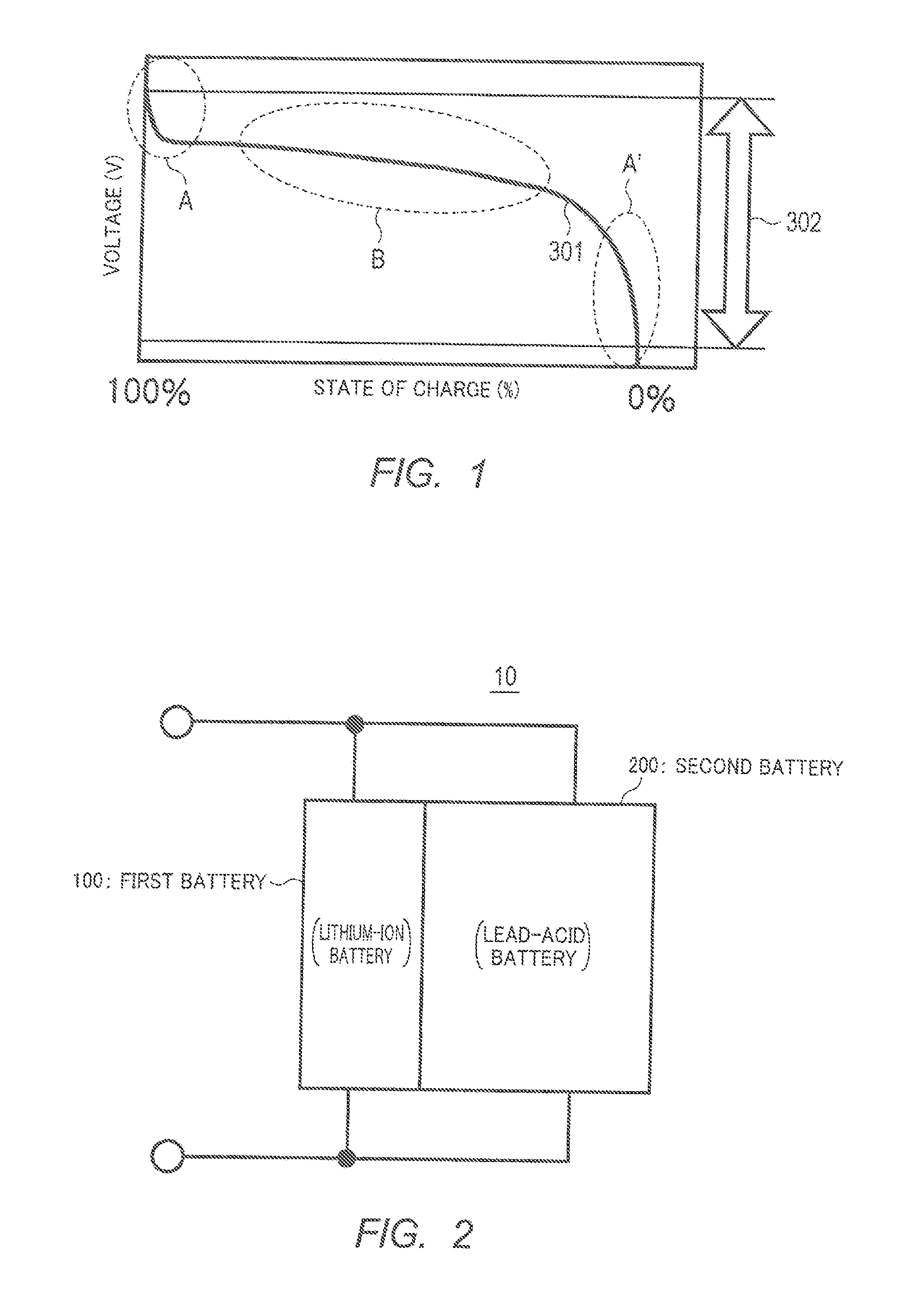
[0027]FIG. 1 is a diagram illustrating an example of a discharge characteristic of a general secondary battery (hereinafter, referred to as “battery”). In FIG. 1, the horizontal axis represents the state of charge (SOC) [%] within a range from 100% to 0%, and the vertical axis represents the voltage [V]. In addition, the terms “initial phase” and “terminal phase,” and “start phase” and “end phase” are used in the following description with the direction in which discharge proceeds, as the basis.

[0028]As illustrated in FIG. 1, in discharge curve 301, which is a discharge curve of a general battery, when discharge continues, the state of charge decreases (i.e., the remaining charge capacity decreases), and the voltage decreases with the decrease in the state of charge. The discharge init...


PUM


Abstract

The battery system is a combined system of a first battery and a second battery. The discharging curve (discharging characteristic) (311) of the first battery has a stable region (B1). The discharging curve (discharging characteristic) (321) of the second battery has a stable region (B2) in the range of voltage lower than the voltage in the stable region (B1) of the first battery and also has an unstable region (A2) in the range of voltage overlapping the voltage in the stable region (B1) of the first battery. The first battery and the second battery are connected in parallel so that, in a discharging process, the discharging state of the entire battery shifts from the stable region (B1) of the first battery to the stable region (B2) of the second battery.

Description

TECHNICAL FIELD[0001]The present invention relates to a battery system to be applied to an electric vehicle, for example.BACKGROUND ART[0002]Heretofore, lead-acid batteries, which are relatively low-priced and well-proven in use, have been widely used as power supplies for electric automobiles, for example. Meanwhile, lithium-ion batteries, which are high-voltage-available and include high-energy density, have also been used as the power supplies in recent years.[0003]However, the charge receiving performance of lead-acid batteries is low, so that it is difficult to efficiently store regenerative energy which is available during braking of vehicles such as electric automobiles (hereinafter, simply referred to as “vehicle” or “vehicles”). Meanwhile, lithium-ion batteries involve high manufacturing costs, and it is difficult to increase the capacity of lithium-ion batteries. For this reason, sufficiently ensuring the power required to start the engine of a vehicle, using lithium-ion b...

Claims


Application Information

Patent Timeline
Patent Type & Authority Applications(United States)
IPC IPC(8): H02J7/00
CPCH02J7/0021H02J7/0063H02J7/007184H02J7/00714
Inventor SUGIYAMA, SHIGEYUKIAOKI, MAMORUNAKAKITA, MANABUNAKAKITA, KAZUSHIGEIIDA, TAKUMA
Owner MAMORU AOKI
Why Eureka
Try Eureka