Synchronous reluctance motor and rotor for synchronous reluctance motor
a synchronous reluctance and synchronous technology, applied in the direction of magnetic circuit rotating parts, dynamo-electric machines, magnetic circuit shape/form/construction, etc., can solve the problems of field weakening control, mechanical strength and thermal durability of permanent magnets, etc., to increase torque and power factor, the effect of raising the salient pole ratio
- Summary
- Abstract
- Description
- Claims
- Application Information
AI Technical Summary
Benefits of technology
Problems solved by technology
Method used
Image

Examples
first embodiment
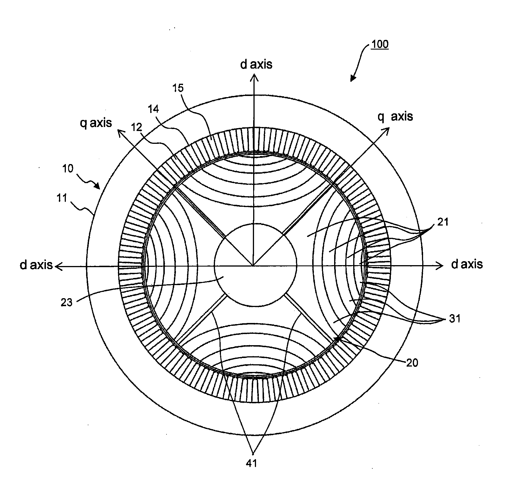
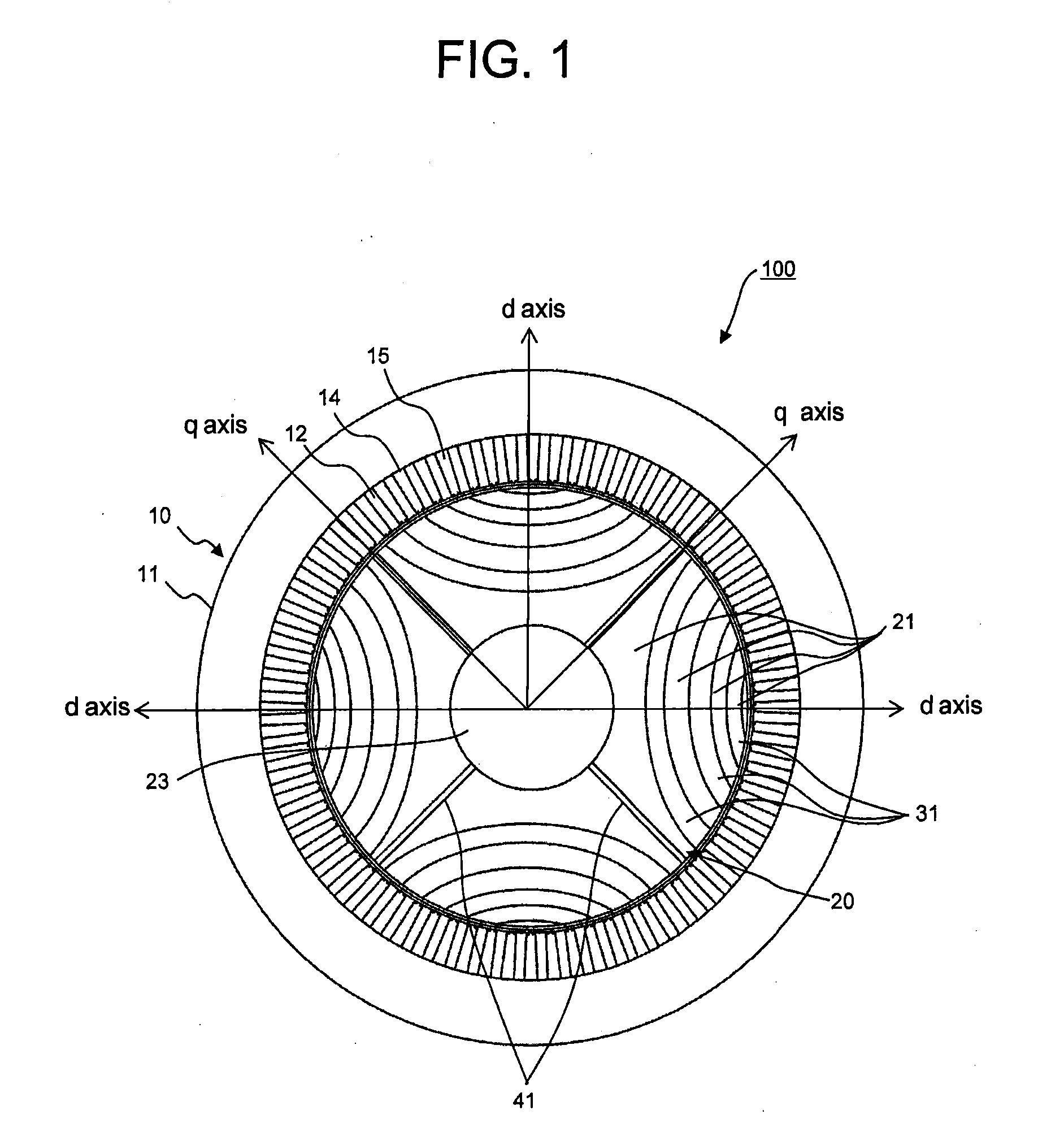
[0027]FIG. 1 is a cross-sectional view of a synchronous reluctance motor, which is perpendicular to the direction of a rotation axis, according to a first embodiment. FIG. 2 is a detailed, partial cross-sectional view of the synchronous reluctance motor, which is perpendicular to the direction of the rotation axis, according to the first embodiment. FIG. 2 is a cross-sectional view of one-fourth of the synchronous reluctance motor. However, FIG. 2 is a diagram showing the one-fourth portion only because of ease of explanation. This does not mean that the synchronous reluctance motor can be divided on a one-fourth basis.
[0028]A synchronous reluctance motor 100 includes, in a housing (not shown), a stator 10 and a rotor 20.
[0029]The stator 10 includes a stator core 11 and a plurality of stator teeth 12.
[0030]The stator core 11 has a structure in which electromagnetic steel sheets, which are thin plates produced by adding silicon to iron, in order to reduce an eddy current loss, are st...
second embodiment
[0067]FIG. 8 is a cross-sectional view of a synchronous reluctance motor of a second embodiment, which is perpendicular to the direction of a rotation axis. The present embodiment is a variant of the first embodiment.
[0068]A star-shaped rotor shaft 50 includes four radial plates 51, which extend toward a radial-direction outer side. The four radial plates 51 are arranged in such a way as to be spaced out in a circumferential direction and extend in the direction of a rotation axis of the rotor 20. What is shown here is the four radial plates 51. However, the number of radial plates 51 is not limited to four. A plurality of radial plates 51, e.g., six radial plates 51, may be provided.
[0069]The radial plates 51 of the second embodiment are disposed in regions corresponding to where the q-axis direction flux barriers 41 are formed in the first embodiment. The star-shaped rotor shaft 50 is made of nonmagnetic material. Accordingly, as in the case of the q-axis direction flux barriers 4...
third embodiment
[0083]FIG. 10 is a partial cross-sectional view showing details of a cross section of a synchronous reluctance motor of a fourth embodiment, which is perpendicular to the direction of a rotation axis. The present embodiment, too, is a variant of the first embodiment.
[0084]According to the first embodiment, the d-axis peripheral flux barriers 31 and the q-axis direction flux barriers 41 are air layers. In the case of the fourth embodiment, d-axis peripheral permanent magnets 33, which are permanent magnets, are provided as d-axis peripheral flux barriers.
[0085]According to the present embodiment, which is configured described above, the d-axis peripheral flux barriers are permanent magnets 33. Therefore, it is possible to form magnetic barriers, as in the case of the first embodiment.
[0086]Moreover, the q-axis direction flux barriers 41 are air layers, and act in the same way as in the first embodiment. Therefore, the salient pole ratio (Lq / Ld) becomes larger, increasing the torque a...
PUM
 Abstract
Description
Claims
Application Information
 - R&D
- Intellectual Property
- Life Sciences
- Materials
- Tech Scout
- Unparalleled Data Quality
- Higher Quality Content
- 60% Fewer Hallucinations
Browse by: Latest US Patents, China's latest patents, Technical Efficacy Thesaurus, Application Domain, Technology Topic, Popular Technical Reports.
© 2025 PatSnap. All rights reserved.Legal|Privacy policy|Modern Slavery Act Transparency Statement|Sitemap|About US| Contact US: help@patsnap.com