Gearbox for a hybrid powertrain and method to control such a gearbox

a hybrid powertrain and gearbox technology, applied in the field of gearboxes, can solve the problems of increasing the size and weight of the gearbox, affecting the reliability and lifetime of the gearbox, and limited space available for the drive arrangement in the vehicl

Active Publication Date: 2016-02-25
SCANIA CV AB
View PDF9 Cites 30 Cited by
  • Summary
  • Abstract
  • Description
  • Claims
  • Application Information

AI Technical Summary

Benefits of technology

[0038]The term “torque balance” is here used to denote a condition in which a torque acts on a ring gear arranged at the epicyclic gear, corresponding to the product of the torque that acts on the planet gear carrier of the epicyclic gear and the gear exchange ratio of the planet gear, while at the same time a torque acts on the sun gear of the epicyclic gear, corresponding to the product of the torque that acts on the planet gear carrier and (1-the gear exchange ratio of the planet gear). In the case in which two of the component parts of the epicyclic gear, sun gear, ring gear and planet gear carrier, are connected by means of a coupling unit, this coupling unit transfers no torque between the components of the epicyclic gear when torque balance is prevalent. The coupling unit can in this way be displaced in a simple manner, and the components of the epicyclic gear disengaged.

Problems solved by technology

The space available for the drive arrangement in a vehicle is often limited.
This results in the size and weight of the gearbox increasing.
Wear arises in cases in which the gearbox contains lamellar clutches, which wear influences the reliability and lifetime of the gearbox.

Method used


Image

  • Gearbox for a hybrid powertrain and method to control such a gearbox
  • Gearbox for a hybrid powertrain and method to control such a gearbox
  • Gearbox for a hybrid powertrain and method to control such a gearbox

Examples


Embodiment Construction

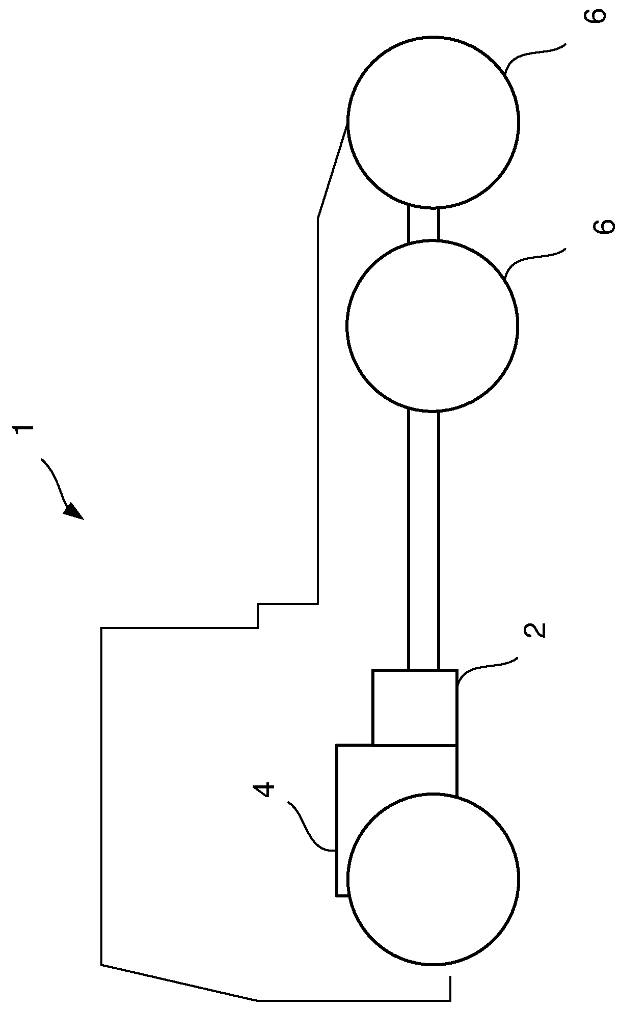
[0046]FIG. 1 shows schematically a side view of a vehicle 1 that comprises a gearbox 2 according to the present invention. A combustion engine 4 is connected to the gearbox 2 and the gearbox 2 is further connected to the driving wheels 6 of the vehicle 1.

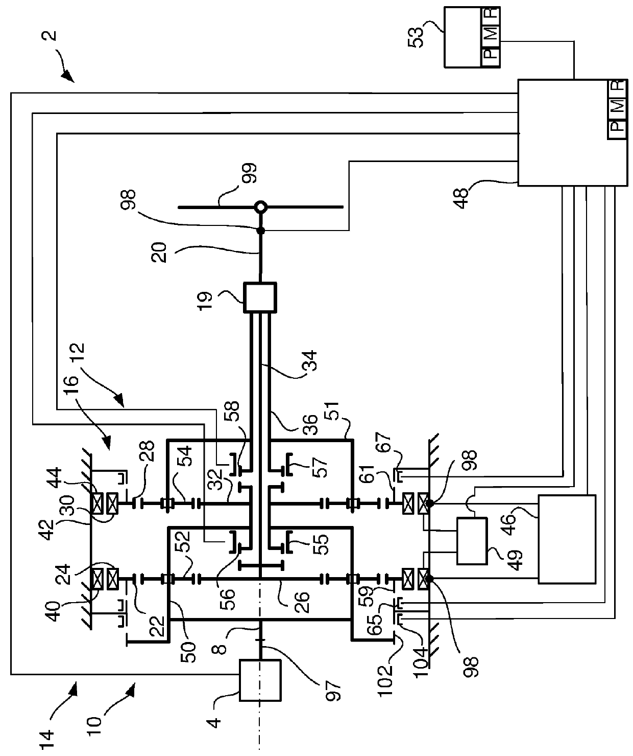
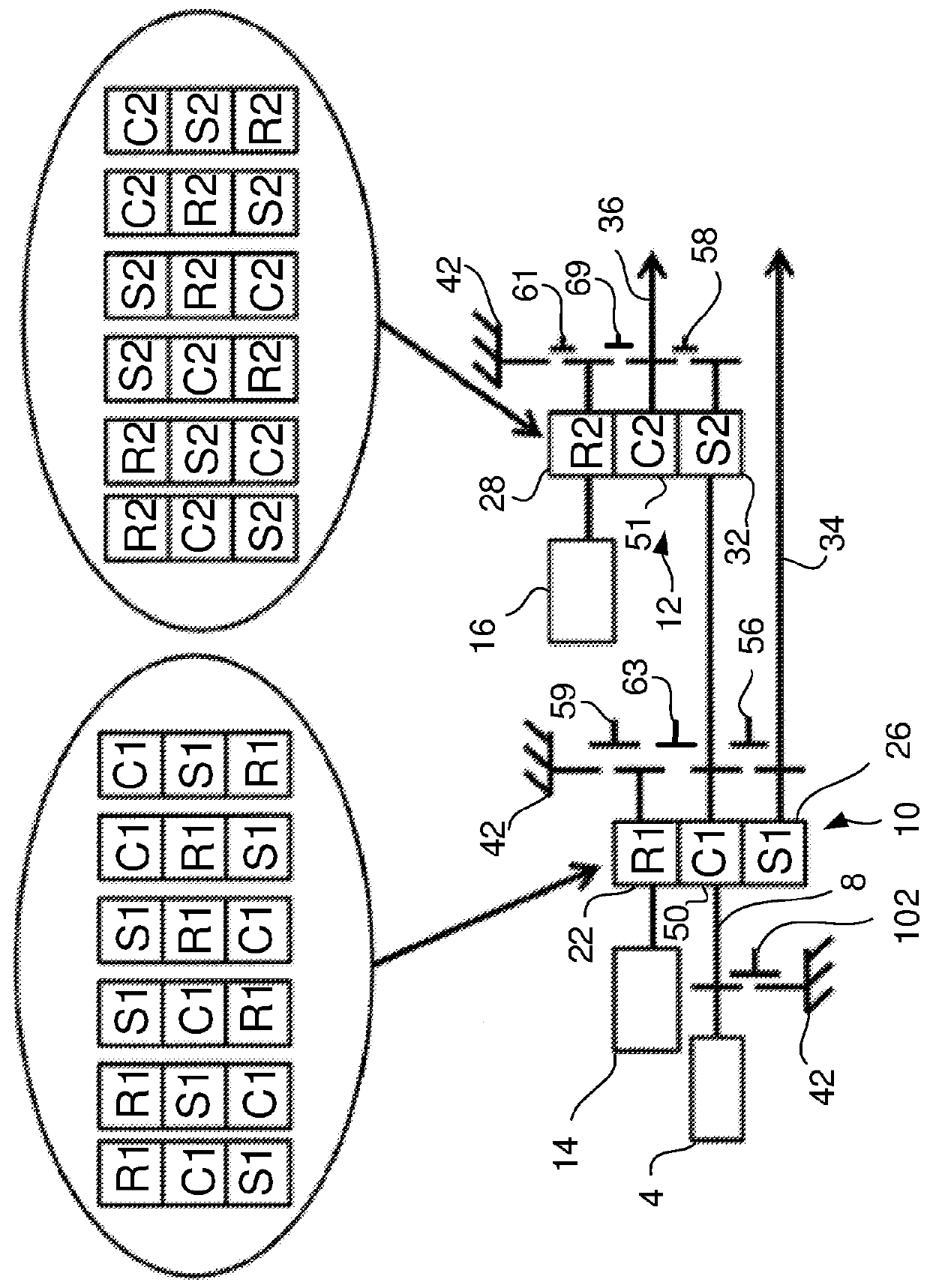
[0047]FIG. 2 shows a schematic side view of the gearbox 2 according to the present invention. The gearbox 2 comprises an input shaft 8, first and second epicyclic gears 10 and 12, first and second electrical machines 14 and 16, and an output shaft 20. The first epicyclic gear 10 has a first ring gear 22, to which a first rotor 24 at the first electrical machine 14 is connected. The first epicyclic gear 10 has also a first sun gear 26. The second epicyclic gear 12 has a second ring gear 28, to which a second rotor 30 at the second electrical machine 16 is connected. The second epicyclic gear 12 has a second sun gear 32. The first and second sun gears 26 and 32 are arranged coaxially. According to the design that is shown in FIG. 2, a...


PUM


Abstract

A gearbox having an input shaft (8) and an output shaft (20); a first epicyclic gear (10) connected to the input shaft (8); a second epicyclic gear (12) connected to the first epicyclic gear (10); a first electrical machine (14) connected to the first epicyclic gear (10); a second electrical machine (16) connected to the second epicyclic gear (12); a first main shaft (34) connected to the first epicyclic gear (10); a second main shaft (36) connected to the second epicyclic gear (12). A first coupling unit (56) disengagingly connects two rotatable components (22, 26, 50) at the first epicyclic gear (10), and a second coupling unit (58) disengagingly connects two rotatable components (28, 32, 51) at the second epicyclic gear (12), such that at least one of the rate of revolution and the torque at the first and the second main shafts (34, 36) can be influenced by controlling at least one of the first and the second coupling units (56, 58) to a condition of the rotatable components (22, 26, 50; 28, 32, 51) that is engaged or disengaged. Also a vehicle (1) having such a gearbox (2), a method to control such a gearbox (2), a computer program (P) to control a gearbox, and a computer program product comprising program code for an electronic control unit (48) or another computer (53) in order to implement the method.

Description

BACKGROUND AND PRIOR ART[0001]The present invention concerns a gearbox according to the introduction to claim 1. The invention concerns also a vehicle that comprises such a gearbox according to the introduction to claim 15, a method to control such a gearbox according to the introduction to claim 16, a computer program to control such a gearbox according to the introduction to claim 21, and a computer program product comprising program code according to the introduction to claim 22.[0002]Hybrid vehicles can be driven by a primary engine, which may be a combustion engine, and a secondary engine, which may be an electrical machine. The electrical machine is equipped with at least one energy store, such as an electrochemical energy store, for the storage of electrical energy, and regulating equipment in order to regulate the flow of electrical energy between the energy store and the electrical machine. The electrical machine can in this way alternate between working as an engine and as...

Claims


Application Information

Patent Timeline
Patent Type & Authority Applications(United States)
IPC IPC(8): F16H3/66B60K6/365F16H3/00F16H61/04
CPCF16H3/66F16H3/006F16H61/0403B60K6/365Y10S903/91F16H2200/2064F16H2200/2094Y10S903/945F16H2200/2007B60K1/02B60K6/445B60K6/547F16H2037/101B60K6/387B60K2006/381B60Y2400/421Y02T10/62B60W10/08F16H3/091F16H3/72F16H3/0915F16H3/725B60W10/06B60K6/40B60W20/00
Inventor LINDSTROM, JOHANBJORKMAN, MATHIASPETTERSSON, NIKLASBERGQUIST, MIKAEL
Owner SCANIA CV AB
Why Eureka
Try Eureka