Tilting disc check valve

Active Publication Date: 2016-02-25
ZHUZHOU SOUTHERN VALVE
View PDF22 Cites 4 Cited by
  • Summary
  • Abstract
  • Description
  • Claims
  • Application Information

AI Technical Summary

Benefits of technology

[0010]A purpose of the invention is to provide a diaphragm control slider type tilting disc check valve, so as to solve the technical problem of slow closing failure of two-stage closing, correct an unreasonable eccentric des

Problems solved by technology

At present, a check valve mounted at a water outlet of a water pump is capable of automatically realizing pump starting when valve is closed and two-stage closing without any other additional device has many problems in terms of structure and use.
② An eccentric design of the large valve plate is unreasonable and free of gravity centre check, and the completely closing of the large valve plate requires backflow water, which may cause a phenomenon of collision during valve closing, high backflow, long reversal time of the water pump, high reversal rotating velocity and potential safety hazards; and a metal hard sealing form of a sealing pair is not allowed due to the existence of phenomena of collision and impact.
③ After the whole valve is closed, the valve rod serves as a maximum force applicator, and maxim

Method used


Image

  • Tilting disc check valve
  • Tilting disc check valve
  • Tilting disc check valve

Examples


Embodiment Construction

[0035]The embodiment of the invention is described below with reference to the drawings in detail, but the invention may be implemented by multiple different manners limited and covered by Claims.

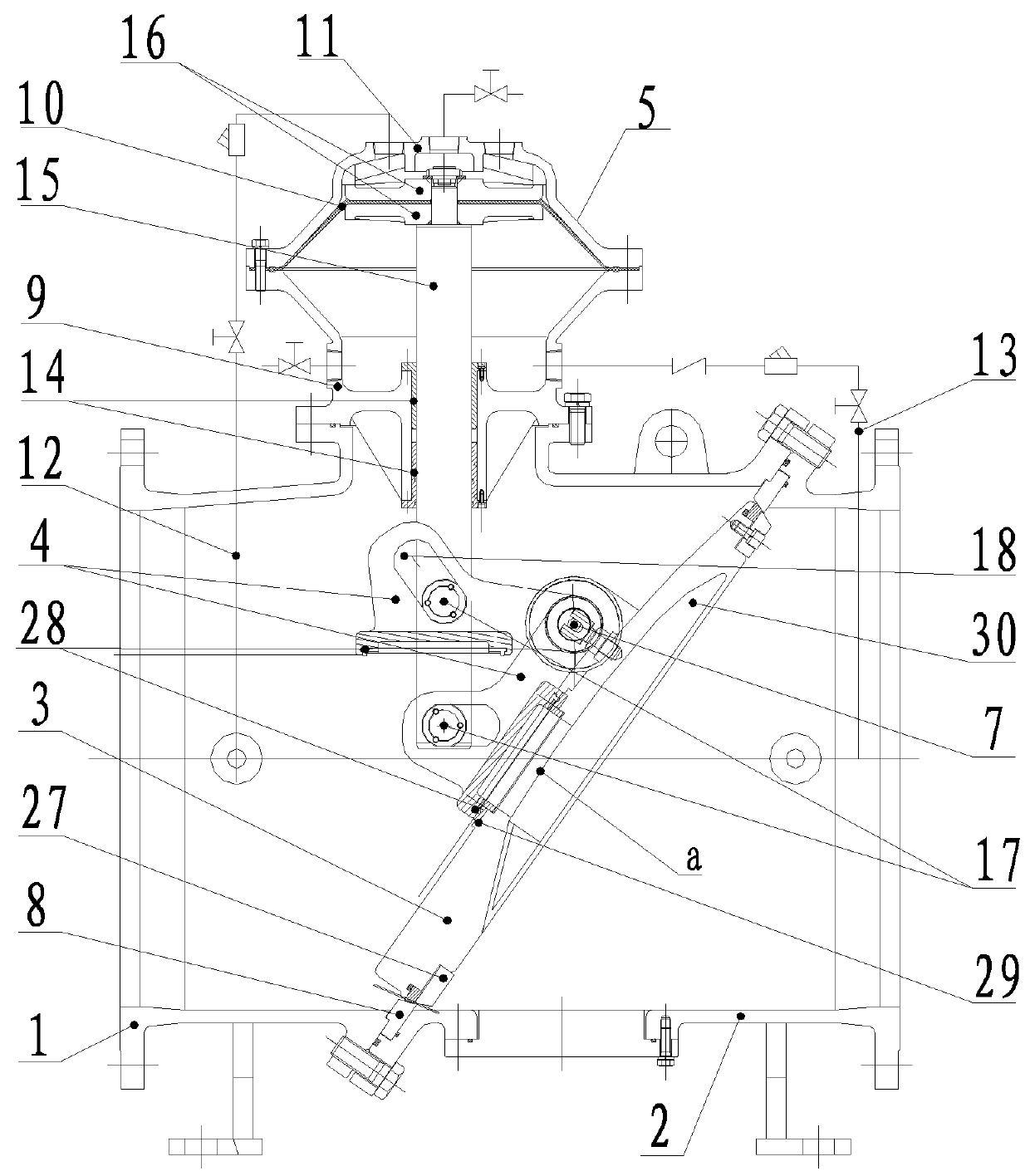
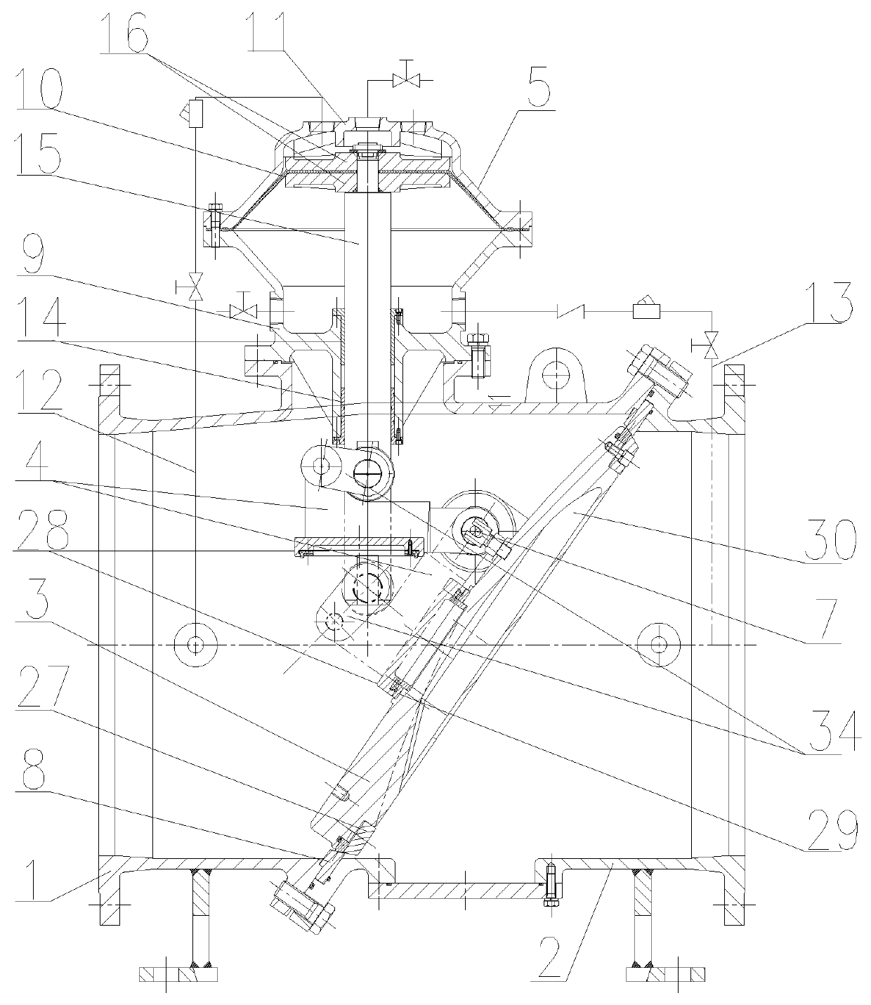
[0036]FIG. 1 is a first structure diagram of a diaphragm control slider type tilting disc check valve according to a preferred embodiment of the invention, FIG. 2 is a second structure diagram of a diaphragm control slider type tilting disc check valve according to a preferred embodiment of the invention, and FIG. 3 is a structure diagram of a diaphragm control connecting rod type tilting disc check valve according to a preferred embodiment of the invention. As shown in FIGS. 1, 2 and 3, the tilting disc check valve includes a left valve body 1, a right valve body 2, a diaphragm control group 5, a large valve plate 3 and a small valve plate 4, wherein the left valve body 1 is connected with the right valve body 2 through oblique flanges and bolts; upper parts of the oblique flanges are incl...


PUM


Abstract

The invention discloses a tilting disc check valve, which includes a left valve body (1), a right valve body (2), a large valve plate (3), a small valve plate (4) and a diaphragm control group (5), wherein the left valve body (1) and the right valve body (2) are butted into a whole through oblique openings; the oblique openings are inclined in a manner that upper parts are inclined towards the right valve body (2); the diaphragm control group (5) is arranged on the left valve body (1); the large valve plate (3) is arranged along the oblique openings; the large valve plate (3) is positioned in a valve cavity formed by the left valve body (1) and the right valve body (2); the large valve plate (3) is suspended on shaft holes of the left valve body (3) through valve shafts (6); the small valve plate (4) is connected with the diaphragm control group (5); and the small valve plate (4) is mounted at a slow closing valve port of the large valve plate (3) through a small valve plate pin shaft (7). According to the tilting disc check valve, a two-stage valve closing process where the large valve plate is quickly closed and the small valve plate at a drain hole of the large valve plate is slowly closed within adjustable time can be implemented, and the aims of reducing backflow of a water body and eliminating pump starting and stopping water hammer are fulfilled.

Description

TECHNICAL FIELD OF THE INVENTION [0001]The invention relates to the technical field of check valves, and in particular to a diaphragm type slider control tilting disc check valve mounted at a water outlet of a water pump.BACKGROUND OF THE INVENTION[0002]A check valve is a group arranged in a pipeline to make a medium directionally to flow without backflow, and is used for various pipe networks more and more widely. At present, a check valve mounted at a water outlet of a water pump is capable of automatically realizing pump starting when valve is closed and two-stage closing without any other additional device has many problems in terms of structure and use.[0003]{circle around (1)} A slow closing small valve plate (or called a slow closing cam) is connected with a valve rod through a hinge (or a chain plate) with a sliding chute, there is a free travel, the valve rod cannot completely control the position of the slow closing small valve plate, and in a running process of the valve,...

Claims


Application Information

Patent Timeline
IPC IPC(8): F16K15/18F16K1/20F16K47/02
CPCF16K15/181F16K47/023F16K1/20F04B53/001F04B53/102F04B53/1087F16K1/2021F16K31/1266F16K39/024F16K39/028F16K15/1821Y10T137/7841
Inventor HUANG, JINGLUO, JIANQUNGUI, XINCHUNTANG, AIHUAYIN, JIANGUODONG, ZHEN
Owner ZHUZHOU SOUTHERN VALVE
Why Eureka
Try Eureka