

Indoor unit for air conditioning devices
- Summary
- Abstract
- Description
- Claims
- Application Information
AI Technical Summary
Benefits of technology
Problems solved by technology
Method used
Image

Examples
Embodiment Construction
[0026]Embodiments of the present invention will be described in detail below with reference to the drawings. The following description of embodiments is merely an illustrative one in nature, and does not intend to limit the scope of the present invention or applications or uses thereof.
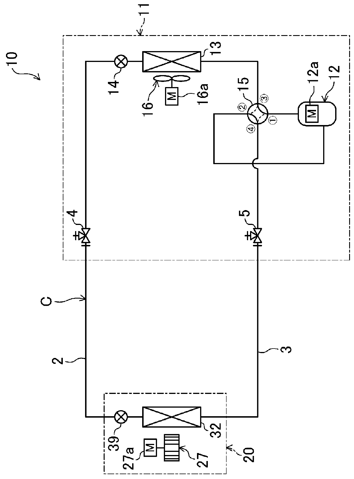
[0027]An embodiment of the present invention is an air conditioning device (10) configured to cool and heat indoor air. As illustrated in FIG. 1, the air conditioning device (10) includes an outdoor unit (11) installed outdoors and an indoor unit (20) installed indoors. The outdoor unit (11) and the indoor unit (20) are connected with each other through two communication pipes (2, 3), which thus forms a refrigerant circuit (C) in this air conditioning device (10). In the refrigerant circuit (C), a refrigerant injected therein is circulated to perform a vapor compression refrigeration cycle.
[0028]
[0029]The outdoor unit (11) is provided with a compressor (12), an outdoor heat exchanger (13), an outdoor ...
PUM
 Abstract
Description
Claims
Application Information