Uninterruptible power-supply system

Active Publication Date: 2016-02-25
HITACHI LTD
View PDF5 Cites 18 Cited by
  • Summary
  • Abstract
  • Description
  • Claims
  • Application Information

AI Technical Summary

Benefits of technology

[0013]According to the present invention, when the DC voltage is applied to the three-phase AC reactor at the time of the storage battery discharge, the magne

Problems solved by technology

The leakage magnetic flux becomes a noise, and there is a possibility to cause a prob

Method used


Image

  • Uninterruptible power-supply system
  • Uninterruptible power-supply system
  • Uninterruptible power-supply system

Examples


first embodiment

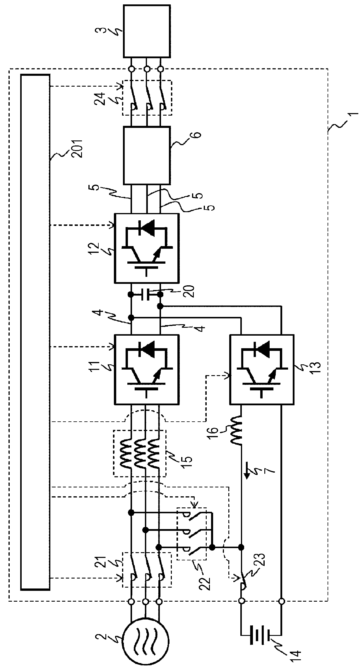
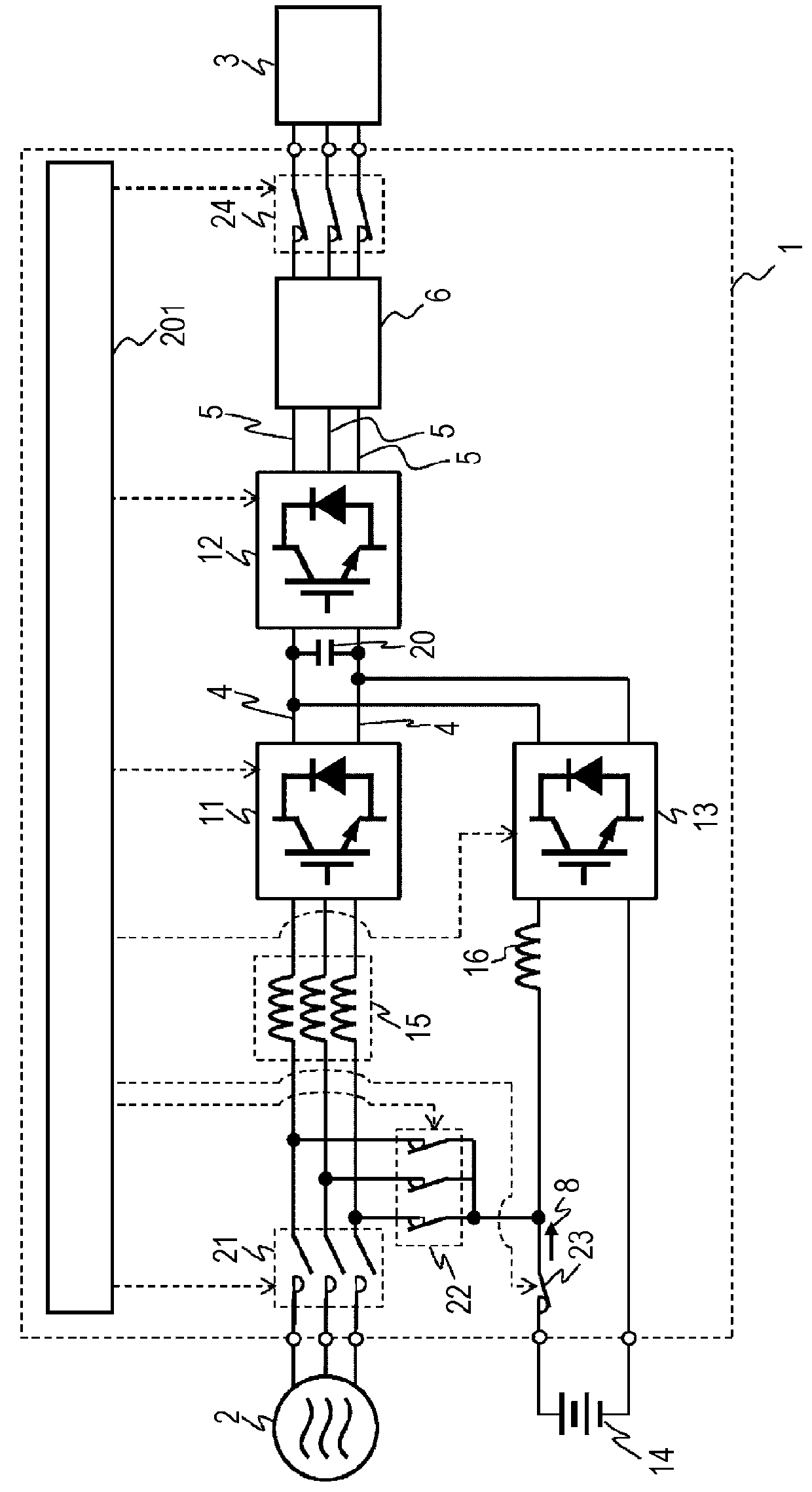
[0033]A first embodiment of the present invention will be described with reference to FIGS. 1 to 12. FIG. 1 is a simple circuit diagram of an UPS 1 of a case where a power is normally supplied from a commercial power supply 2. The present system is a double-conversion UPS system which can continue to supply the power without instantaneous interruption at the time of interruption of the power supply. A three-phase AC power from the commercial power supply 2 is supplied to a converter 11 via a stationary power-supply-side switch 21 and a three-phase AC reactor 15 having a five-leg iron core. Then, the three-phase AC power is converted from AC into DC by the converter 11 which is a rectifier circuit. The reactor 15 in a previous stage of the converter 11 is a part of a filter to remove a harmonic generated in a case where the converter 11 converts the power. After the rectification by the converter 11, a DC voltage 4 smoothed by a capacitor 20 is applied to an inverter 12 and reversely...

second embodiment

[0055]A second embodiment of the present invention will be described with reference to FIG. 13. FIG. 13 is a magnetic circuit diagram of a case where a DC voltage is applied to all the three phases of a three-phase AC reactor having a four-leg iron core. In this way, even when the three-phase AC reactor having the four-leg iron core is arranged in a previous stage of the converter 11, a magnetic circuit is closed. Therefore, an UPS similar to that of the first embodiment can be configured.

third embodiment

[0056]Next, a third embodiment of the present invention will be described with reference to FIG. 14. A three-phase AC reactor 15 having a five-leg iron core in a previous stage of a converter 11 and a reactor 16 in a previous stage of a charge / discharge chopper 13 can be integrated into a single reactor. FIG. 14 is a magnetic circuit diagram of the reactor having the six-leg iron core at the time of commercial power supply abnormality. An output end of a three-phase coil is connected to the converter 11. The three-phase coil is formed by respectively winding coils 102r, 102s, and 102t around magnetic leg iron cores 101r, 101s, and 101t. In addition, an output end of the coil formed by winging a coil 102k around a magnetic leg iron core 101k is connected to the charge / discharge chopper 13. Magnetic leg iron cores 105a and 105b which do not have the coils winding around them are included as a zero-phase magnetic leg iron core, and all the magnetic leg iron cores are joined to yoke iro...


PUM


Abstract

When the power is normally supplied from the commercial power supply, the storage battery is charged by reducing the DC voltage by the charge/discharge chopper. The switching unit is provided in the previous stage of the converter. When the commercial power supply is in an abnormal state, the three-phase AC converter is operated as three discharge choppers connected in parallel by supplying the power of the storage battery to the converter and boosting the power by the switching element included in the converter. The power of the storage battery is boosted by the charge/discharge chopper, and a part of the discharging power is supplied. One three-phase AC reactor is provided in the previous stage of the converter, and the three-phase AC reactor has three coils, magnetic leg iron cores having the coils winding around them, and one leg without a coil winding around it connected in parallel.

Description

BACKGROUND OF THE INVENTION[0001]1. Field of the Invention[0002]The present invention relates to a uninterruptible power-supply system, and specifically to a uninterruptible power-supply system suitable for rectifying a three-phase AC by a converter including a power semiconductor module, converting the power into AC power of which the voltage and frequency can be changed by an inverter, and reducing a charging voltage of the storage battery or boosting a discharging voltage of the same.[0003]2. Description of the Related Art[0004]An uninterruptible power-supply system (referred to as UPS below) is an apparatus for using a power conversion apparatus to stably supply the power without an interruption of the power supply to a load when a commercial power supply and the like which is a stationary power supply has an abnormality. As IT use has been innovated in recent years, a demand of the UPS in a data center and the like has increased. Since the UPS for the data center is laid near c...

Claims


Application Information

Patent Timeline
IPC IPC(8): H02J9/06H01F27/24
CPCH01F27/24H02J9/062
Inventor KONISHI, YUICHIRONISHIHARA, ATSUOHORIUCHI, KEISUKE
Owner HITACHI LTD
Why Eureka
Try Eureka