Photoacoustic Imager

a technology of photoacoustic imager and imager, which is applied in the field of photoacoustic imager, can solve the problem of not being able to efficiently generate an acoustic wave in specimens, and achieve the effect of efficiently generating an acoustic wav

Inactive Publication Date: 2016-03-03
PREXION
View PDF7 Cites 5 Cited by
  • Summary
  • Abstract
  • Description
  • Claims
  • Application Information

AI Technical Summary

Benefits of technology

[0008]The present invention has been proposed in order to solve the aforementioned problem, and an object of the present invention is to provide a photoacoustic imager capable of making a specimen efficiently generate an acoustic wave.

Problems solved by technology

In other words, the photoacoustic image generator according to the aforementioned Japanese Patent Laying-Open No. 2012-196308 conceivably has such an inconvenience that the same causes excessive generation of an acoustic wave having a frequency higher than the maximum frequency detectable by the ultrasonic probe and not contributing to imaging of the acoustic wave (the specimen).
Therefore, the photoacoustic image generator according to the aforementioned Japanese Patent Laying-Open No. 2012-196308 conceivably has such a problem that the same cannot make the specimen efficiently generate an acoustic wave due to the generation of the acoustic wave not contributing to the imaging.

Method used


Image

  • Photoacoustic Imager
  • Photoacoustic Imager
  • Photoacoustic Imager

Examples


first embodiment

[0045]The structure of a photoacoustic imager 100 according to a first embodiment of the present invention is described with reference to FIGS. 1 to 5.

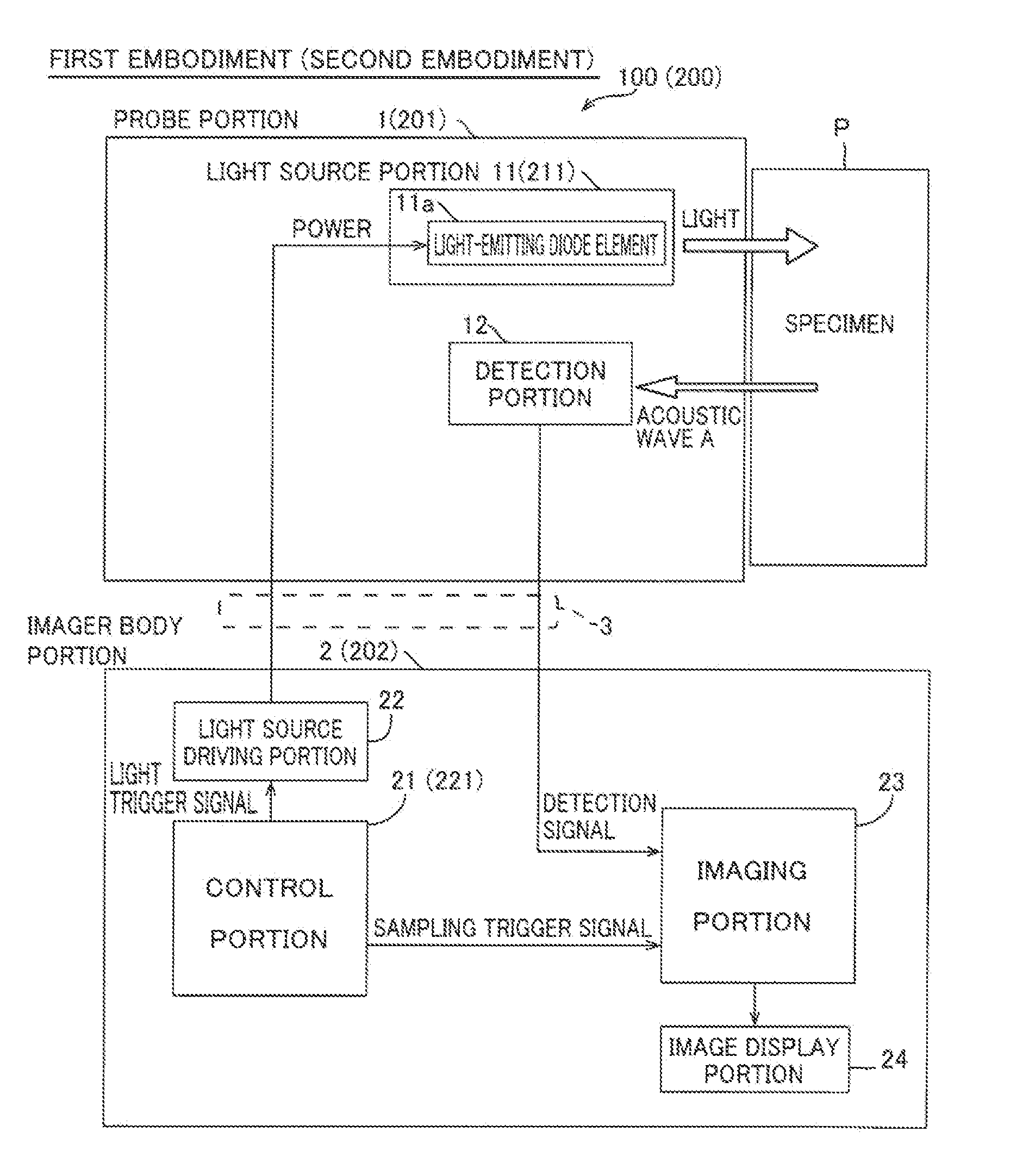
[0046]The photoacoustic imager 100 according to the first embodiment of the present invention is provided with a probe portion 1 and an imager body portion 2, as shown in FIG. 1. The photoacoustic imager 100 is also provided with a cable 3 connecting the probe portion 1 and the imager body portion 2 with each other.

[0047]The probe portion 1 is so configured that the same is grasped by an operator and arranged on a surface of a specimen P (such as a surface of a human body). The probe portion 1 is configured to be capable of applying light to the specimen P, to detect an acoustic wave A, described later, generated by the specimen P and to transmit the acoustic wave A to the imager body portion 2 through the cable 3 as a detection signal.

[0048]The imager body portion 2 is configured to process and image the detection signal detected by ...

second embodiment

[0094]The structure of a photoacoustic imager 200 according to a second embodiment of the present invention is now described with reference to FIGS. 1 and 7. According to the second embodiment, a light source portion 211 is configured to set pulsed light emitted therefrom to a pulse width tw of at least 100 ns and not more than 500 ns.

[0095]As shown in FIG. 1, the photoacoustic imager 200 according to the second embodiment is provided with a probe portion 201 and an imager body portion 202. The probe portion 201 includes the light source portion 211, while the imager body portion 202 includes a control portion 221. The light source portion 221 is provided therein with 108 light-emitting diode elements 11a, similarly to the light source portion 11 according to the first embodiment.

[0096]According to the second embodiment, the control portion 221 is configured to perform control of transmitting a light trigger signal to a light source driving portion 22 for a time of at least a period...

third embodiment

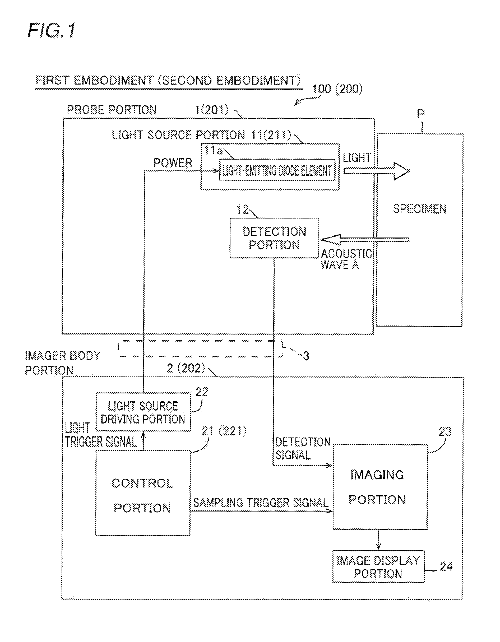
[0110]The structure of a photoacoustic imager 300 according to a third embodiment of the present invention is now described with reference to FIGS. 2 and 8. According to the third embodiment, a light source driving portion 322 is configured to supply current to a light source portion 11 so that the maximum value of current flowing in light-emitting diode elements 11a is at least the rated current of the light-emitting diode elements 11a and the density thereof is not more than 120 A / mm2.

[0111]As shown in FIG. 2, the photoacoustic imager 300 according to the third embodiment is provided with a control portion 321 and the light source driving portion 322.

[0112]According to the third embodiment, the light source driving portion 322 is configured to supply current to the light source portion 11 so that the maximum value of the current flowing in the light-emitting diode elements 11a is at least the rated current of the light-emitting diode elements 11a and the density thereof is not mor...


PUM


Abstract

This photoacoustic imager includes a light source portion and a detection portion, and is configured to set pulsed light emitted by the light source portion to a pulse width tw expressed in the following expression, assuming that fmax represents the maximum frequency of an acoustic wave A detected by the detection portion:0.5 / fmax≦tw≦1 / fmax

Description

BACKGROUND OF THE INVENTION[0001]1. Field of the Invention[0002]The present invention relates to a photoacoustic imager, and more particularly, it relates to a photoacoustic imager including a detection portion detecting an acoustic wave resulting from light applied to a specimen and an ultrasonic wave applied to and reflected by the specimen.[0003]2. Description of the Background Art[0004]A photoacoustic imager including a detection portion detecting an acoustic wave resulting from light applied to a specimen and an ultrasonic wave applied to and reflected by the specimen is known in general, as disclosed in Japanese Patent Laying-Open No. 2012-196308, for example.[0005]The aforementioned Japanese Patent Laying-Open No. 2012-196308 discloses a photoacoustic image generator including an ultrasonic probe detecting a photoacoustic signal resulting from a laser beam applied to a specimen and a reflected acoustic signal applied to and reflected by the specimen. This photoacoustic image ...

Claims


Application Information

Patent Timeline
Patent Type & Authority Applications(United States)
IPC IPC(8): A61B5/00
CPCA61B5/742G01N29/343A61B8/4411G05D25/02A61B8/4477A61B5/0095G01N29/2418A61B8/4444H05B45/46H05B47/12Y02B20/40
Inventor NAKATSUKA, HITOSHIAGANO, TOSHITAKA
Owner PREXION
Why Eureka
Try Eureka