
Liquid ejection head

Active Publication Date: 2016-03-03
CANON KK
View PDF2 Cites 1 Cited by
  • Summary
  • Abstract
  • Description
  • Claims
  • Application Information

AI Technical Summary

Benefits of technology

The patent is about a system that separates liquid into two parts: a main liquid channel and a chamber where pressure is applied. This separation reduces resistance at the inlets and outlets of the pressure chambers, improving the accuracy of the liquid ejection. The liquid is supplied and discharged through the main liquid channel, which helps remove bubbles from the liquid while printing. The technical effect of this system is better performance and reliability of printing with liquid ink.

Problems solved by technology

It is known that the presence of bubbles in the pressure chamber significantly reduces the droplet ejection performance of liquid ejection heads.
However, the suction recovery, which needs to stop printing, reduces the production efficiency and wastes a large quantity of liquid.
This is disadvantageous for commercial liquid ejection apparatuses that output high-quality images at a high speed in terms of time and cost.
This causes a non-uniform pressure distribution in the common liquid channel due to channel resistance, exerting different negative pressures on the different pressure chambers, which may cause variations in ejection performance.
Since the channel resistance depends on the viscosity of the liquid, larger variations in ejection performance can occur in printing with high-viscosity liquid, such as UV ink and solder paste, causing degradation of image quality.

Method used


Image

  • Liquid ejection head
  • Liquid ejection head
  • Liquid ejection head

Examples


first embodiment

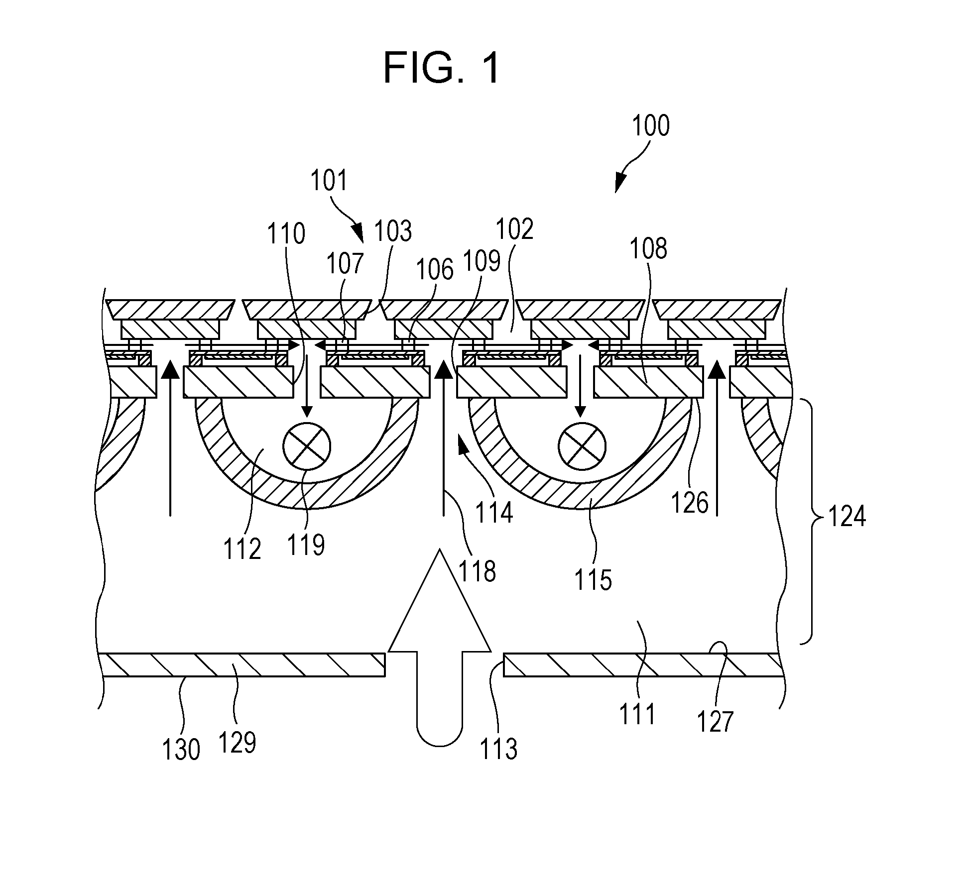
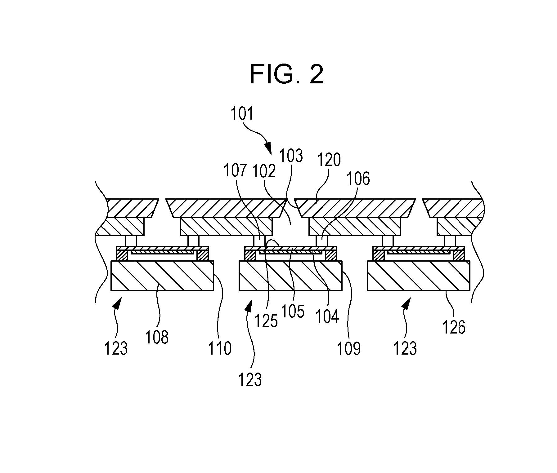
[0020]FIG. 1 is a schematic cross-sectional view of a liquid ejection head installed in a liquid ejection apparatus according to a first embodiment of the present invention. FIG. 2 is a schematic cross-sectional view of a liquid ejection substrate of the liquid ejection head. A liquid ejection head 100 includes a liquid ejection substrate 101. The liquid ejection substrate 101 has a plurality of liquid ejection sections 123 disposed in two dimensions. Each of the liquid ejection sections 123 includes a pressure chamber 102 having an ejection port 103, a piezoelectric element 104 to which a diaphragm 105 is bonded, a liquid supply channel 106, and a liquid recovery channel 107. The pressure chamber 102 temporarily holds liquid, such as ink, for use in printing. Each ejection port 103 corresponds to each individual pressure chamber 102 and communicates with the pressure chamber 102. The piezoelectric element 104 is a pressure device that presses liquid in the pressure chamber 102. The...

second embodiment

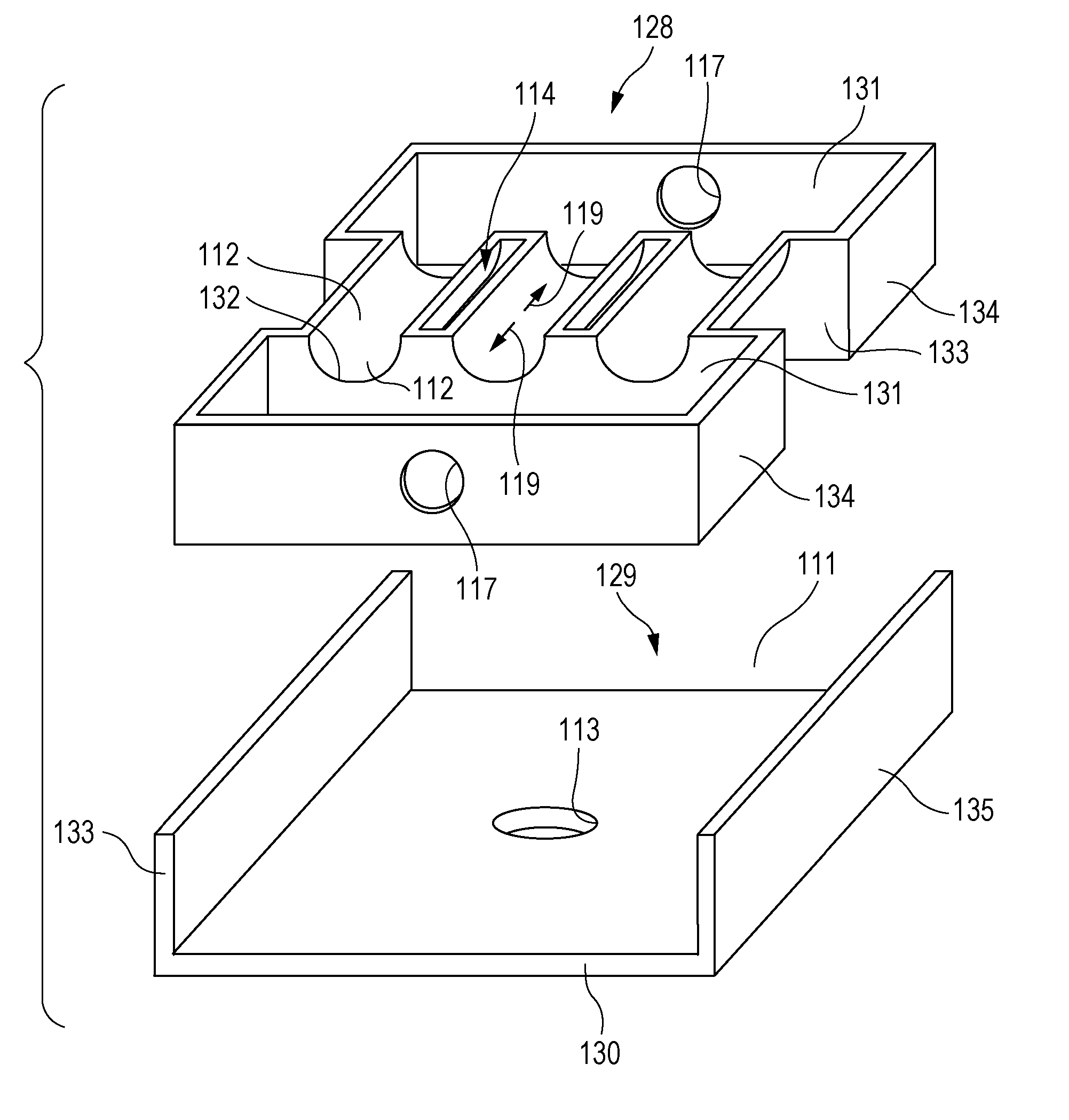
[0032]The present invention can also be applied to a Gould's liquid ejection head, that is, a liquid ejection head in which pressure chambers are surrounded by a piezoelectric material, and pressure is applied to liquid in the pressure chamber due to the extension and retraction in a radial direction of the pressure chamber. FIG. 7 is an exploded perspective view of a Gould's liquid ejection head according to an embodiment of the present invention. FIG. 8 is a schematic cross-sectional view of the same.

[0033]A liquid ejection head 100 includes an ejection-port formed member 120 having ejection ports 103 and a piezoelectric element 104 including pressure chambers 102 and liquid recovery channels 107. The pressure chambers 102 have the shape of a tube or a column communicating with the ejection ports 103 at one end and communicating with the first common liquid chamber 111 at the other end. In this embodiment, the liquid in the pressure chambers 102 is pressed by the piezoelectric ele...


PUM


Abstract

A liquid ejection head includes a liquid ejection substrate and a liquid reservoir. The liquid ejection substrate includes a plurality of liquid ejection sections. The liquid ejection sections include pressure chambers configured to hold liquid and ejection ports communicating with the pressure chambers. The pressure chambers each include a pressure unit configured to apply pressure to the liquid in each of the pressure chambers. The pressed liquid is ejected through the ejection ports. The liquid reservoir is in contact with a back of the liquid ejection substrate opposite to the ejection ports. The liquid reservoir is partitioned into at least one common liquid channel and a first common liquid chamber. The common liquid channel communicates with one of inlets and outlets of the plurality of pressure chambers. The first common liquid chamber communicates with another of the inlets and the outlets.

Description

BACKGROUND OF THE INVENTION[0001]1. Field of the Invention[0002]The present invention relates to a liquid ejection head that ejects liquid.[0003]2. Description of the Related Art[0004]Liquid ejection apparatuses that eject liquid such as ink to record images on a recording medium are generally equipped with a liquid ejection head that ejects liquid. Known examples of a mechanism for ejecting liquid from the liquid ejection head include a mechanism that uses a pressure chamber whose capacity can be varied with an piezoelectric element and a mechanism that uses a heating element that heats liquid to generate bubbles, thereby generating pressure. The pressure generated using these mechanisms causes the liquid in the pressure chamber to be ejected through ejection ports at an end of the pressure chamber. The pressure chamber is under a minute negative pressure. The negative pressure and the capillary action of the ejection ports are balanced to hold the interface of the liquid in the ej...

Claims


Application Information

Patent Timeline
IPC IPC(8): B41J2/175B41J2/145
CPCB41J2/175B41J2/145B41J2/14233B41J2002/14419B41J2002/14459B41J2202/12
Inventor NAKAMURA, YOHEITAMURA, YASUYUKI
Owner CANON KK
Learn More