Electronic control unit and in-vehicle video system

a technology of electronic control unit and video system, which is applied in the field of electronic control unit and in-vehicle video system, can solve the problems of cost and time required to process video image data, and achieve the effect of convenient visualization

Active Publication Date: 2016-03-03
KOITO MFG CO LTD
View PDF3 Cites 14 Cited by
  • Summary
  • Abstract
  • Description
  • Claims
  • Application Information

AI Technical Summary

Benefits of technology

[0012]According to the ECU and the in-vehicle video system of the invention, since the video image data captured by the camera is processed at the different compression ratios to be displayed on at least the two portions

Problems solved by technology

However, with the method of changing the angle of view by using a lens, a peripheral area of a vehicle body that is displayed on a monitor does not coincide with a peripheral area of the vehicle body that is seen on a side rear-view mirror, and therefore, there is a possibility that a dangerous situation is called for by an error made by the driver in grasping an actual distance t

Method used


Image

  • Electronic control unit and in-vehicle video system
  • Electronic control unit and in-vehicle video system
  • Electronic control unit and in-vehicle video system

Examples


Embodiment Construction

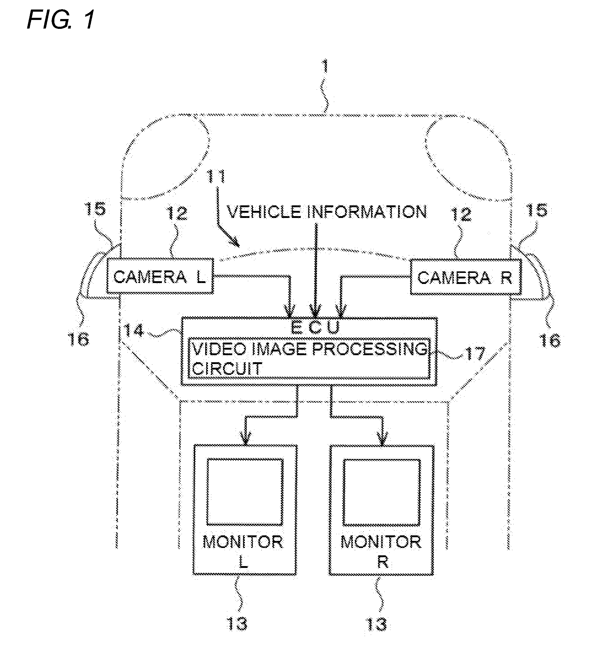
[0024]Hereinafter, an embodiment of the invention will be described based on the drawings. An in-vehicle video system 11 shown in FIG. 1 includes a pair of left and right cameras 12 for capturing images of rear and side areas of a vehicle body 1, a pair of left and right monitors 13 for displaying thereon video images captured by the cameras 12, and an ECU 14 for executing data processing to shape the video images for display on the monitors 13.

[0025]The cameras 12 are accommodated in interiors of housings 15 so as to be oriented to the rear of the vehicle body 1. The housings 15 are used as camera housings or lamp housings and are mounted, for example, on both left and right sides of a front portion of the vehicle body 1. A side turn signal lamp 16, which is an illumination lamp, is provided on an external surface of each housing 15. The monitors 13 are disposed in front of or near a driver's seat.

[0026]The ECU 14 is separated from the cameras 12 and the monitors 13 and is set at a...


PUM


Abstract

An in-vehicle video system includes cameras that capture rear and side areas of a vehicle body, monitors that display video images captured by the cameras on screens thereof, and an ECU that shapes the video images that are displayed on the monitors. The cameras are accommodated in housings that are provided on left and right sides of a vehicle body, and side turn signal lamps are provided individually on external surfaces of the housings. The ECU controls a video image processing circuit so that the video images of the rear and side areas of the vehicle body are displayed on two portions of the screen of the monitor at different compression ratios and that the compression ratios change according to vehicle information.

Description

CROSS-REFERENCE TO RELATED APPLICATION[0001]The present application claims the benefit of priority of Japanese Patent Application No. 2014-172896, filed on Aug. 27, 2014, which is incorporated herein by reference.TECHNICAL FIELD[0002]The present invention relates to an electronic control unit for executing data processing to shape a video image of a peripheral area of a vehicle body that is captured by an onboard camera so as to display the shaped video image on an onboard monitor and an in-vehicle video system including the electronic control unit.BACKGROUND ART[0003]A technology has conventionally been known in which a camera and a monitor are used in place of a side rear-view mirror and a video image of a peripheral area of a vehicle body that is taken by the camera is displayed on the monitor disposed in a passenger compartment of a vehicle. For example, JP-A-2003-312359 describes a “vehicle rear view recognition system” in which cameras are set on both left and right sides of a...

Claims


Application Information

Patent Timeline
IPC IPC(8): B60R1/00H04N7/18
CPCB60R1/00B60R2300/105H04N7/181B60R2300/802B60R2300/303
Inventor TATARA, NAOKI
Owner KOITO MFG CO LTD
Why Eureka
Try Eureka