Lock-Up Device For Torque Converter
- Summary
- Abstract
- Description
- Claims
- Application Information
AI Technical Summary
Benefits of technology
Problems solved by technology
Method used
Image

Examples
first exemplary embodiment
[0040][Construction of Torque Converter]
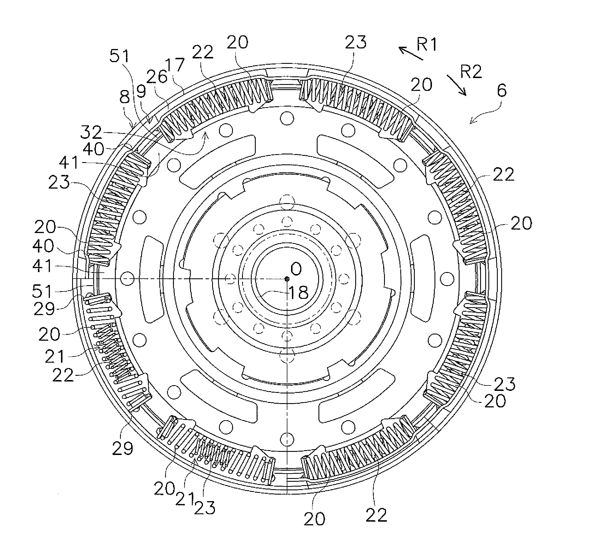
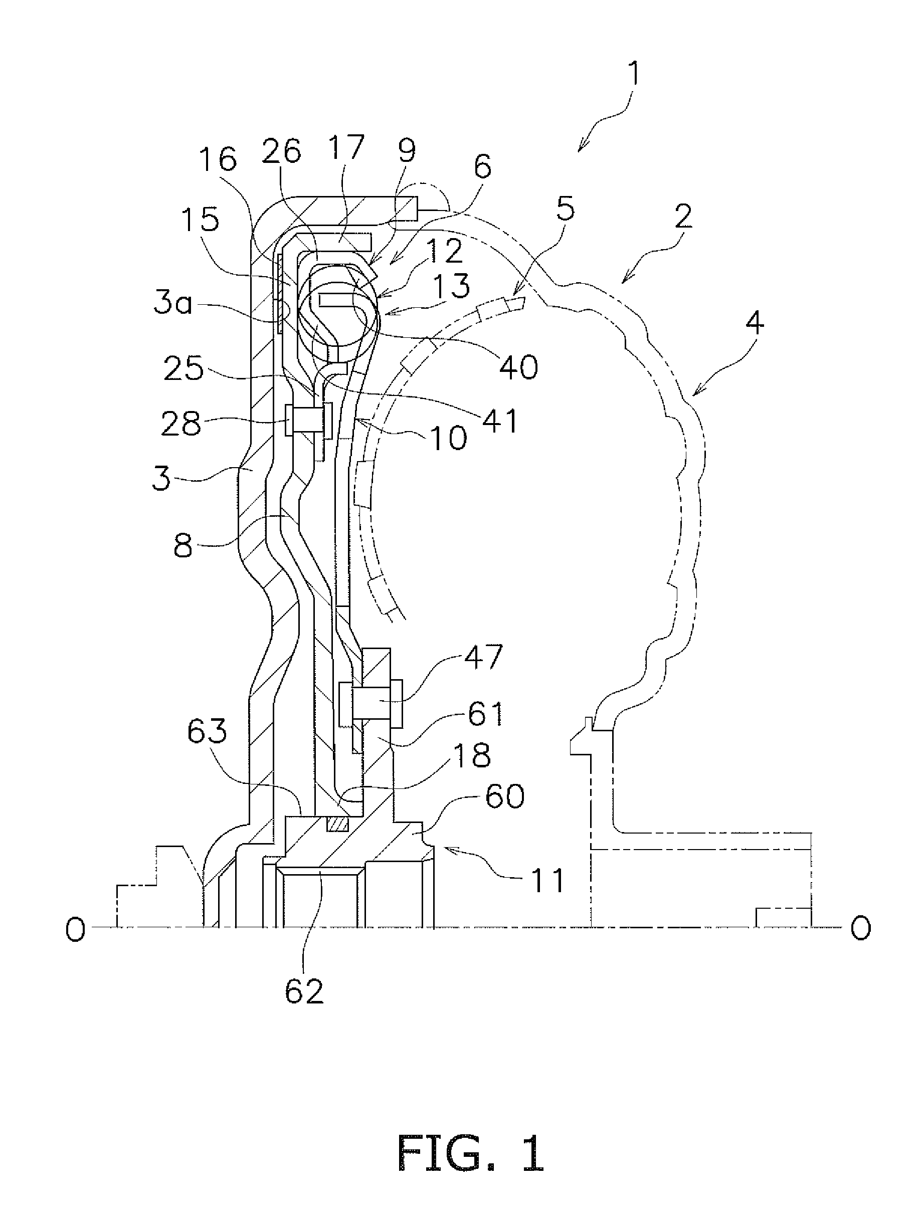
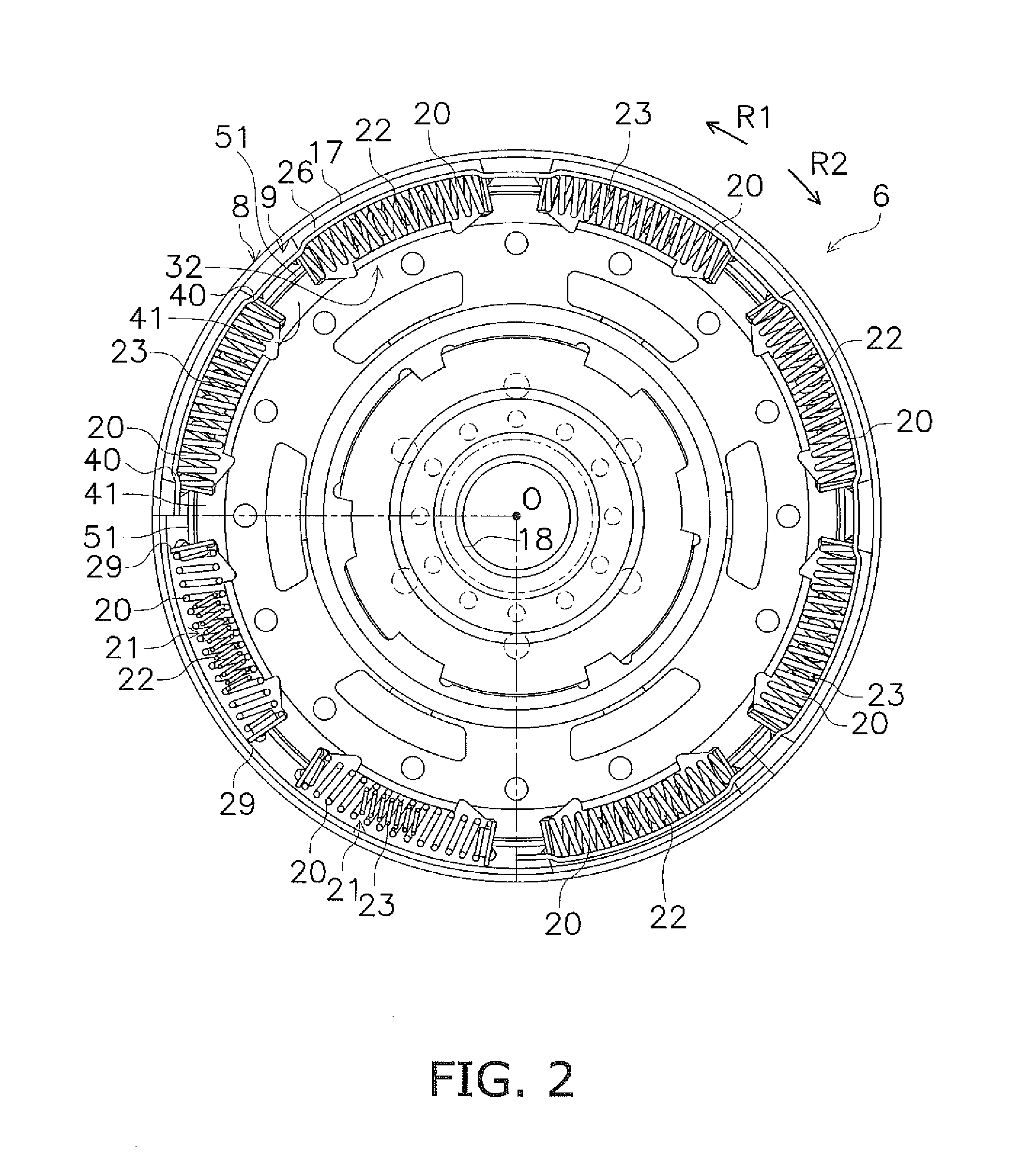
[0041]FIG. 1 shows a schematic vertical cross-sectional view of a torque converter 1 as an exemplary embodiment of the present invention. In FIG. 1, an engine (not shown in the drawing) is disposed on the left side, whereas a transmission (not shown in the drawing) is disposed on the right side. In FIG. 2, an R1 direction indicates a forward rotational direction. Additionally, O-O depicted in FIG. 1 indicates a rotational axis of the torque converter 1, arrow R1 depicted in FIG. 2 indicates an engine rotational direction, and arrow R2 indicates a rotational direction opposite to the engine rotational direction.
[0042]The torque converter 1 includes a torque converter body 2 and a lock-up device 6. In FIG. 1, the torque converter body 2 is mainly composed of a front cover 3, an impeller 4, a turbine 5 and so forth. The construction of the torque converter body 2 is similar to that of a well-known torque converter body, and therefore will be brie...
second exemplary embodiment
[0084]FIG. 4 shows a lock-up device according to a second exemplary embodiment. Except for the constructions of the small coil springs 21, the constructions of components of the lock-up device in the second exemplary embodiment are similar to those of their corresponding components of the lock-up device in the first exemplary embodiment. Therefore, components similar to their corresponding components in the first exemplary embodiment will not be herein explained. Additionally, in FIG. 4, reference signs, assigned to components of the first exemplary embodiment, are similarly assigned to their corresponding components. It should be noted that the construction of the torque converter body of the second exemplary embodiment is also similar to that of the torque converter body in the first exemplary embodiment. Hence, the torque converter body will not be also explained herein.
[0085]Components different from their corresponding components in the first exemplary embodiment will be herein...
third exemplary embodiment
[0107]FIGS. 6 and 7 show a lock-up device according to a third exemplary embodiment. Except for the constructions of the drive plate 9, the driven plate 10, the small coil springs 21 and parallel coil springs 27, the constructions of components of the lock-up device in the third exemplary embodiment are similar to those of their corresponding components of the lock-up device in the first exemplary embodiment. Therefore, components similar to their corresponding components in the first exemplary embodiment will not be herein explained. Additionally, in FIGS. 6 and 7, reference signs, assigned to components in the first exemplary embodiment, are similarly assigned to their corresponding components. It should be noted that the construction of the torque converter body in the third exemplary embodiment is also similar to that of the torque converter body in the first exemplary embodiment. Hence, the torque converter body will not be also explained herein.
[0108]Components different from ...
PUM
 Abstract
Description
Claims
Application Information
 - R&D
- Intellectual Property
- Life Sciences
- Materials
- Tech Scout
- Unparalleled Data Quality
- Higher Quality Content
- 60% Fewer Hallucinations
Browse by: Latest US Patents, China's latest patents, Technical Efficacy Thesaurus, Application Domain, Technology Topic, Popular Technical Reports.
© 2025 PatSnap. All rights reserved.Legal|Privacy policy|Modern Slavery Act Transparency Statement|Sitemap|About US| Contact US: help@patsnap.com