Aiming apparatus using digital magnification

a technology of digital magnification and aiming apparatus, which is applied in the direction of mountings, telescopes, instruments, etc., can solve the problems of reducing the accuracy of digital magnification, affecting the hitting accuracy, and increasing the deviation of the position so as to improve the accuracy of high digital magnification, the accuracy of the ballistic compensation point, and the effect of increasing the output voltag

Inactive Publication Date: 2016-03-03
SINTAI OPTICAL SHENZHEN CO LTD +1
View PDF3 Cites 27 Cited by
  • Summary
  • Abstract
  • Description
  • Claims
  • Application Information

AI Technical Summary

Benefits of technology

[0007]The invention provides an aiming apparatus using digital magnification to solve the above problems. The aiming apparatus using digital magnification is provided with an increased output voltage at high digital magnification so as to improve the accuracy of high digital magnification, the accuracy of the ballistic compensation point, and the hitting accuracy.

Problems solved by technology

At high digital magnification, any errors of the output voltage may reduce the digital magnification accuracy, increase position deviation of the ballistic compensation point and affect the hitting accuracy because the rotation angle of the magnification ring as well as the output voltage is relatively small.

Method used


Image

  • Aiming apparatus using digital magnification
  • Aiming apparatus using digital magnification
  • Aiming apparatus using digital magnification

Examples


Embodiment Construction

[0029]The following description is made for the purpose of illustrating the general principles of the invention and should not be taken in a limiting sense. The scope of the invention is best determined by reference to the appended claims.

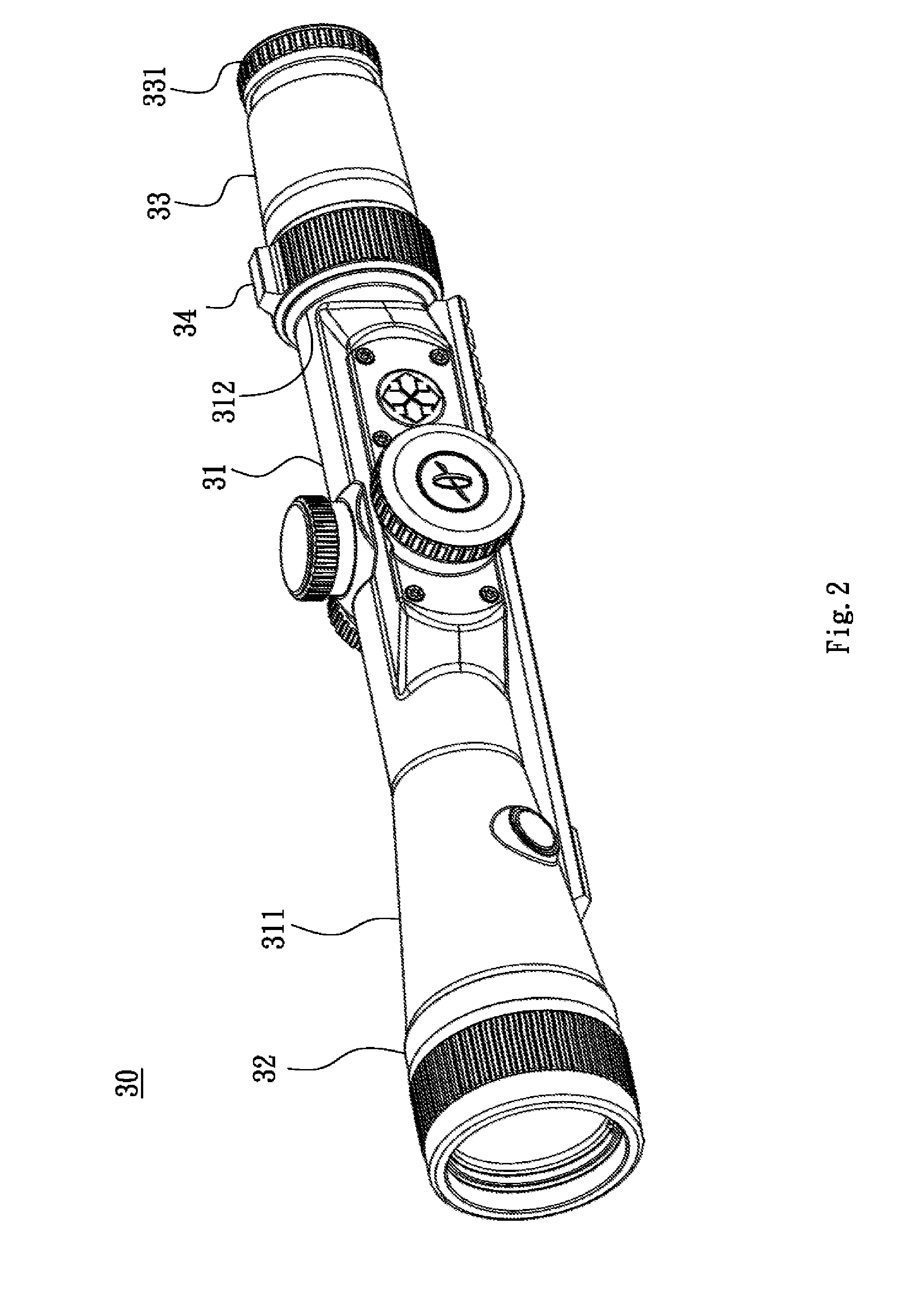
[0030]Referring to FIG. 2, FIG. 2 is a schematic diagram of an aiming apparatus using digital magnification in accordance with an embodiment of the invention. The aiming apparatus using digital magnification 30 includes a main cylinder body 31, an object lens 32, an eyepiece 33 and a magnification ring 34. The main cylinder body 31 includes a front end 311 which is connected to the object lens 32 and a rear end 312 which is connected to the eyepiece 33. A focusing ring 331 is disposed on the surface of the eyepiece 33 and can be rotated to adjust focus. The magnification ring 34 is disposed on the surface of the rear end 312. The inner of the main cylinder body 31 includes an erector device (not shown) and a display unit (not shown). Users can rota...


PUM


Abstract

An aiming apparatus using digital magnification includes a main cylinder body, an object lens, an eyepiece, an erector device and a magnification ring. The main cylinder body includes a front end connecting to the object lens and a rear end connecting to the eyepiece. The erector device is disposed within the main cylinder body and includes an inner tube, an outer tube, a ring resistor board, a pogo pin and a parallel resistor. The inner tube jackets the outer tube. The pogo pin is disposed in the outer tube and contacts the ring resistor board. The ring resistor board connects to the parallel resistor in parallel. The magnification ring is rotatably disposed in the main cylinder body to rotate the outer tube with respect to the inner tube so as to change the contact position of the pogo ring on the ring resistor board.

Description

BACKGROUND OF THE INVENTION[0001]1. Field of the Invention[0002]The invention relates to an aiming apparatus using digital magnification.[0003]2. Description of the Related Art[0004]The present aiming apparatus in operation uses a measured distance of prey and the magnification of the aiming apparatus, through a ballistic compensation formula, to determine a ballistic compensation point. The ballistic compensation point is displayed by the screen of the aiming apparatus for a user to aim at prey before firing. For the present aiming apparatus, accuracy of the ballistic compensation point as well as hitting accuracy significantly depends on magnification accuracy.[0005]An aiming apparatus using digital magnification has a magnification ring to adjust the digital magnification. The output voltage can be changed by rotation of the magnification ring. Different output voltages represent different digital magnifications. It is therefore understood that the accuracy of digital magnificati...

Claims


Application Information

Patent Timeline
Patent Type & Authority Applications(United States)
IPC IPC(8): F41G1/38G02B7/10G02B15/00G02B23/16G02B23/24
CPCF41G1/38G02B23/16G02B7/10G02B15/00G02B23/2446G02B23/10
Inventor CHEN, TUNG-CHING
Owner SINTAI OPTICAL SHENZHEN CO LTD
Why Eureka
Try Eureka