
Moving Multi-Polarization Multi-Transmitter/Receiver Ground Penetrating Radar System and Signal Processing for Buried Target Detection

a multi-polarization, ground-penetration radar technology, applied in the field of ground-penetration radar systems, can solve the problems of multi-transmitter/receiver (array-based) gpr community to exploit synthetic aperture information, and achieve the effects of suppressing surface targets, suppressing the signature of surface clutter, and enhancing the signature of buried structures

Inactive Publication Date: 2016-03-03
UNITED STATES OF AMERICA THE AS REPRESENTED BY THE SEC OF THE ARMY
View PDF3 Cites 47 Cited by
  • Summary
  • Abstract
  • Description
  • Claims
  • Application Information

AI Technical Summary

Benefits of technology

The present invention is a Ground Penetrating Radar (GPR) system that uses multiple polarized antennas and a moving platform to detect buried targets. By separately analyzing the signals from each polarization, the system can form high quality radar images with low artifacts and enhance the signatures of buried targets. The invention also utilizes the properties of radar waves polarization to detect buried structures by separating the echoed signals of the two polarized transmissions. The system can simultaneously transmit diverse and uncorrelated waveforms at different polarizations and has a higher sampling rate than systems that alternate between polarizations.

Problems solved by technology

The failure of the multi-Transmitter / Receiver (array-based) GPR community to exploit synthetic aperture information might have been due to utilization of inaccurate platform motion information.

Method used


Image

  • Moving Multi-Polarization Multi-Transmitter/Receiver Ground Penetrating Radar System and Signal Processing for Buried Target Detection
  • Moving Multi-Polarization Multi-Transmitter/Receiver Ground Penetrating Radar System and Signal Processing for Buried Target Detection
  • Moving Multi-Polarization Multi-Transmitter/Receiver Ground Penetrating Radar System and Signal Processing for Buried Target Detection

Examples


Embodiment Construction

[0035]A specific reference is made to a grace period inventor disclosure at a government symposium as follows: Tuan Ton, David Wong, and Mehrdad Soumekh, “Adaptive Multi-Transceiver Imaging for Forward-Looking Ground Penetrating Radar,” 58th Annual Meeting of the Military Sensing Symposia (MSS) Tri Service Radar Symposium. Ton et al. does not name additional authors other than the named co-inventors of the subject patent application. The Ton et al. presentation in Volume 1 of MSS-TSRS-12-033, 2012 is not available to the public.

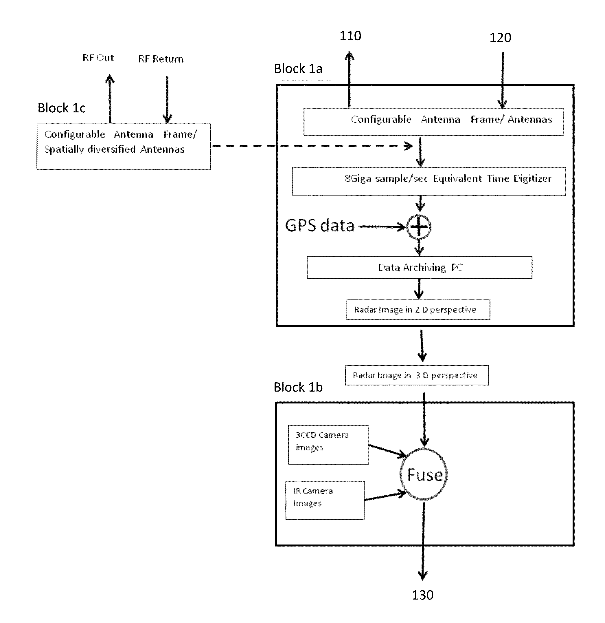
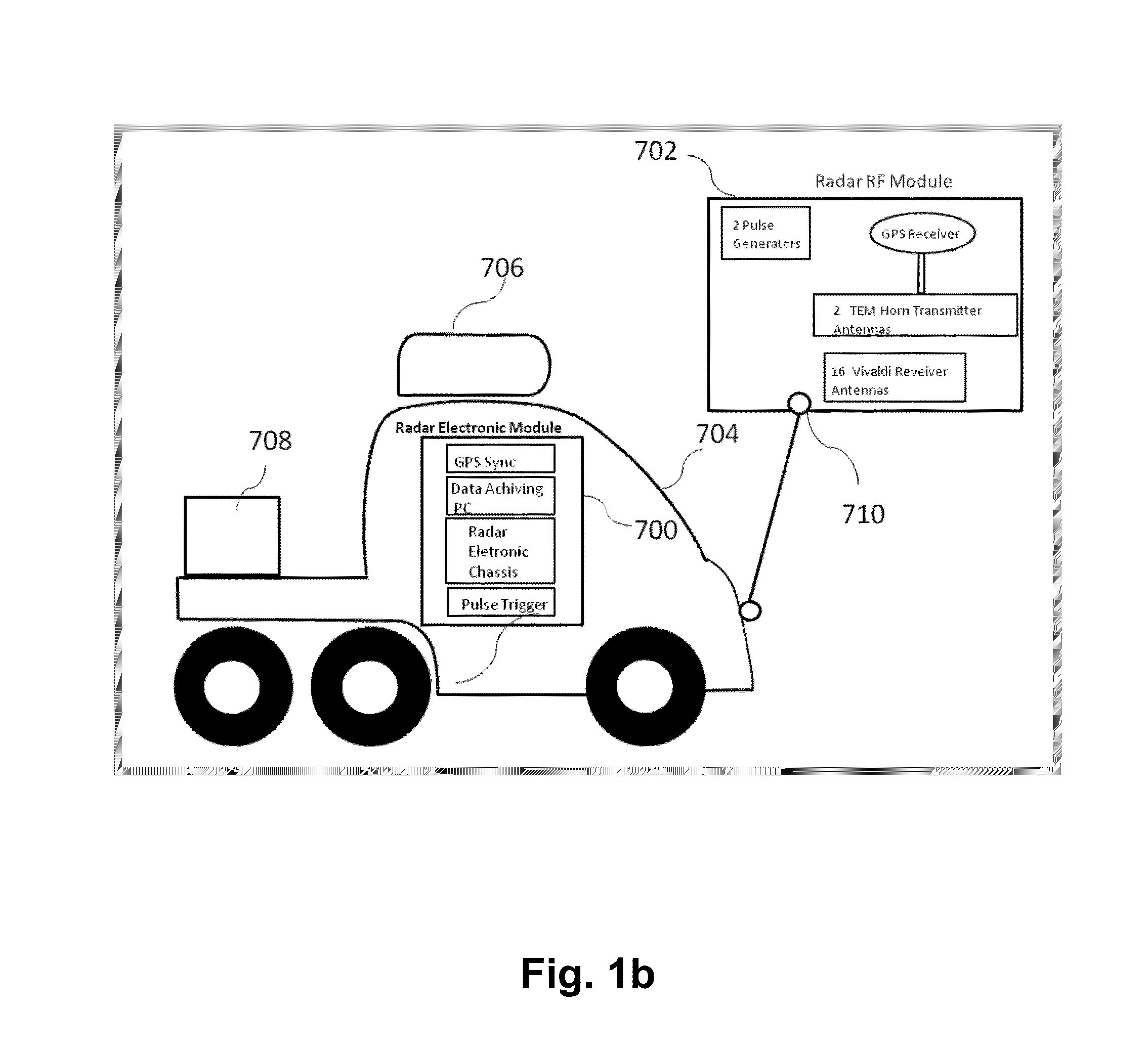
[0036]1. ALARIC Multi-Transmitter / Receiver (Array-Based) GPR: A moving multi-polarization multi-transmitter / receiver Forward Looking Ground Penetrating Radar (FLGPR) system is discussed, e.g., for standoff detection of buried targets within an irradiated scene.

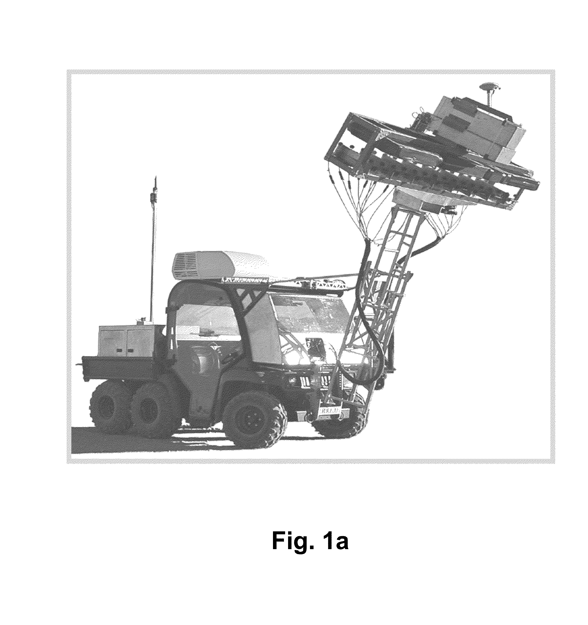
[0037]ALARIC is a prototype radar system (FIG. 1a) designed and constructed by the U.S. Army Night Vision and Electronic Sensors Directorate (NVESD). Shown in FIG. 1a is an exemplary profile view of veh...


PUM


Abstract

A moving ground penetrating radar is comprised of multiple transmitters and receivers with multiple, e.g., Horizontal and Vertical, polarizations to detect buried targets with standoff capability. Novel signal and imaging techniques are used to form high quality radar imagery with low artifacts that are due to various sources of self-induced resonances, e.g., transmitter-receiver coupling, calibration errors, and motion errors in the multi transmitter / receiver channels of the radar system. The irradiated target area image is formed via exploiting both the spatial diversity of the physical multi-transmitter and multi-receiver array and synthetic aperture / array that is generated by the motion of the platform that carries the radar system. The images that are formed from the multiple polarizations are combined to remove surface targets / clutter and, thus, enhance signatures of buried targets.

Description

GOVERNMENT INTEREST[0001]The invention described herein may be manufactured, used, sold, imported, and / or licensed by or for the Government of the United States of America.FIELD OF THE INVENTION[0002]This invention relates in general to ground penetrating radar systems, and more particularly, to multi-polarization and multi-transmitter / receiver ground penetrating radar systems.BACKGROUND OF THE INVENTION[0003]Buried threats have proven to be extremely dangerous on the battlefield. The current preferred method for detecting these buried targets is to use downward-looking ground penetration radar. In general, these radar systems perform adequately when the antenna apparatus is placed close to the ground surface and directly above the target. However, the major drawback of these systems is that they lack standoff capability.[0004]More recently, new emphasis has been placed on a GPR system that exhibits standoff capability. Another key element in defining the utility of these systems is...

Claims


Application Information

Patent Timeline
Patent Type & Authority Applications(United States)
IPC IPC(8): G01S13/88G01S7/02G01S7/40G01S13/02G01S13/86G01S13/89
CPCG01S13/885G01S13/0209G01S13/86G01S7/4004G01S13/867G01S13/89G01S7/024G01S13/90
Inventor TON, TUAN, T.WONG, DAVID, C.SOUMEKH, MEHRDAD
Owner UNITED STATES OF AMERICA THE AS REPRESENTED BY THE SEC OF THE ARMY
Learn More