
Semi-active optical tracking system

a tracking system and semi-active technology, applied in the field of electromagnetic radiation tracking systems, can solve the problems of high cost, difficult acquisition of targets by passive systems, and high cost of active systems, and achieve the effect of enhancing the target signatur

Active Publication Date: 2011-11-01
RAYTHEON CO
View PDF4 Cites 9 Cited by
  • Summary
  • Abstract
  • Description
  • Claims
  • Application Information

AI Technical Summary

Benefits of technology

The present invention relates to a system and method for tracking a target using an illumination source and a detector. The system uses a digital computer or processor to process the electromagnetic radiation reflected off the target and detect its edges. The received radiation is then filtered to remove noise and enhance the target's signature. The system can track the target even in cluttered environments and at ranges up to 100 meters. The invention overcomes the problems of previous tracking systems that used expensive and range-gated sensors. The method includes generating electromagnetic radiation to direct it at the target, receiving the reflected radiation with a track detector, processing the received radiation to identify the edges of the target, and using the information to control a high energy laser to aim at the target. The system and method can be used in a variety of applications, such as for tracking airborne targets or unmanned aerial vehicles.

Problems solved by technology

One problem with such sensors is that passive systems have difficulty acquiring a target in cluttered environments and active systems rely on range-gated sensors and fast switching illuminators, which are expensive.
Many of these tracking methods suffer from a problem of “random walk”, where the heat from the HEL walks the tracker to the edge of the target or completely off the target.

Method used


Image

  • Semi-active optical tracking system
  • Semi-active optical tracking system
  • Semi-active optical tracking system

Examples


Embodiment Construction

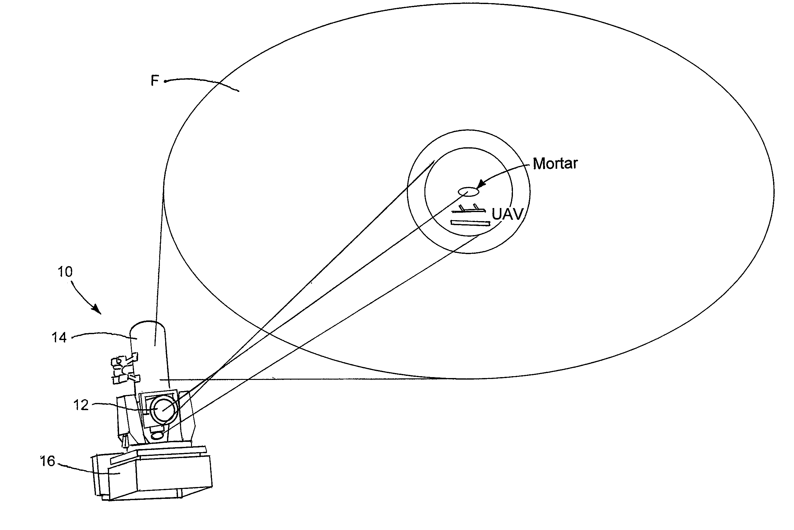
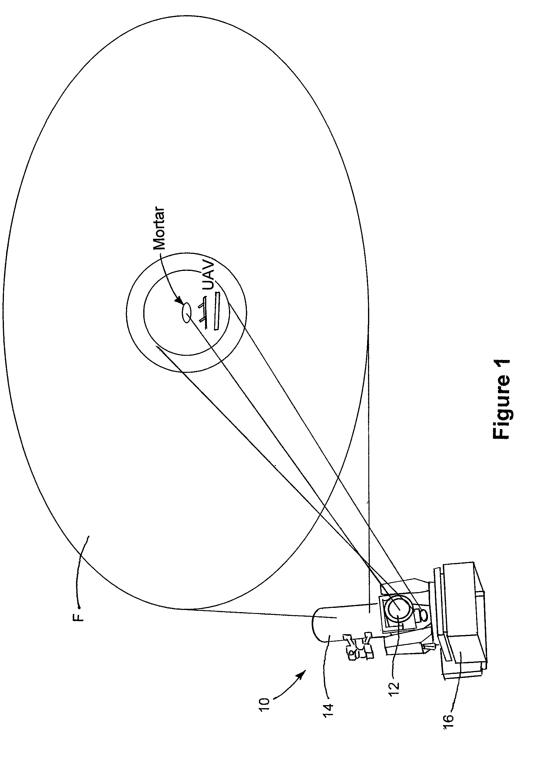
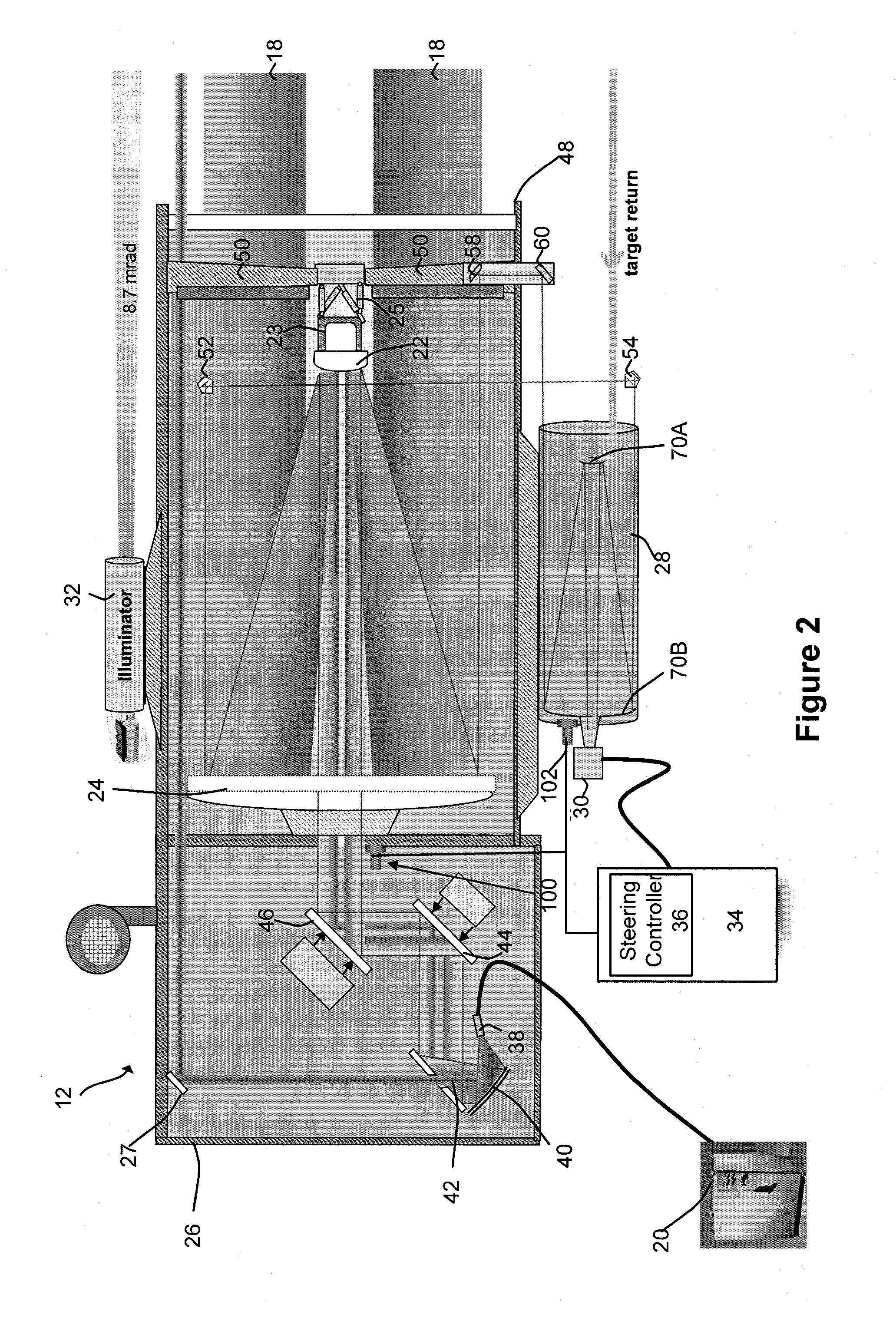
[0024]The present disclosure relates to a tracking system and method for tracking airborne targets. The system generally includes an illuminator for generating electromagnetic radiation to be directed at an airborne target. The illuminator may be in the form of at least one of a solid-state laser, a fiber laser, or a laser diode array. The illuminator generally produces electromagnetic in the form of an output beam having a wavelength between visible (380 to 750 nanometers) and infrared (400 to 700 nanometers) regions of the electromagnetic spectrum. The output beam of the illuminator is directed to a target through a free-space coupled or a fiber-coupled delivery.

[0025]The system further includes a track telescope having a track detector configured to receive electromagnetic radiation reflected from the airborne target.

[0026]A processor is coupled to the track detector and a steering controller for a high energy laser (HEL) to generate a control signal for input to the steering con...


PUM


Abstract

A system and method for tracking an airborne target including an illumination source (e.g., a diode laser array) is used to enhance a target signature and a detector (e.g., a passive high-speed camera) is used to detect to electromagnetic radiation (e.g., infrared radiation) reflected off the target. The received electromagnetic radiation may be processed by a digital computer and passed through a spatial filter that implements a band limited edge detection operation in the frequency domain. The filter may remove low spatial frequencies that attenuate soft edged clutter such as clouds and smoke as well as filter out artifacts and attenuated medium to high spatial frequencies to inhibit speckle noise from the detector as well as speckle from the laser return off the target.

Description

TECHNICAL FIELD[0001]The present invention relates generally to systems and methods for tracking targets using electromagnetic radiation.BACKGROUND OF THE INVENTION[0002]Directed energy weapons and specifically high-energy laser (HEL) weapons are being considered for variety of military applications with respect to a variety of platforms, e.g., spaceborne, airborne and land based systems to name a few. These weapons generally involve the use of a laser or other source of a high-power beam of electromagnetic radiation to track and destroy a target. To achieve mission objectives, directed energy weapons must accurately track the intended target. Accurate tracking of airborne targets is extremely difficult given the presence of clutter (e.g., terrain, clouds, smoke, etc.) and sensor noise. The HEL beam further complicates the situation by generating hot-spots on the target and incandescing the debris, which can “walk” the HEL beam off the intended target.SUMMARY OF THE INVENTION[0003]A...

Claims


Application Information

Patent Timeline
Patent Type & Authority Patents(United States)
IPC IPC(8): G01P3/36G01B11/26
CPCF41G1/34F41G3/145F41G5/08G01S3/7865G06T7/2046G06T2207/30212G06T7/251
Inventor MOSIER, DANIEL J.DENNEY, DWIGHT L.YOON, JOHN
Owner RAYTHEON CO
Learn More