System and method for optimizing wind turbine operation

a technology of voltage regulator and wind turbine, which is applied in the direction of electric generator control, process and machine control, instruments, etc., can solve the problems of increasing or decreasing the voltage of the generator stator, requiring additional cost and/or complexity, and the limitations tend to be more significant for dfig, etc., to achieve the effect of maximizing the margin-to-threshold ratio

Active Publication Date: 2016-03-03
GENERAL ELECTRIC CO
View PDF13 Cites 24 Cited by
  • Summary
  • Abstract
  • Description
  • Claims
  • Application Information

AI Technical Summary

Benefits of technology

[0007]In one aspect, the present disclosure is directed to a method for optimizing operation of a wind turbine. The method includes providing a voltage regulator between a power grid and the wind turbine. The voltage regulator is configured to control at least one voltage condition of the wind turbine. Another step includes monitoring, via one or more sensors, at least one operating condition and at least one voltage condition of the wind turbine. The method also includes comparing, via a controller, at least one of the operating condition or the voltage condition with a predetermined threshold to determine a margin-to-threshold ratio. Thus, a further step includes controlling the voltage regulator based on the comparison so as to maximize the margin-to-threshold ratio.

Problems solved by technology

Further, grid operating practices and failures may lead to increased or decreased voltages on the generator stator, which reflect onto the generator rotor and the DC link.
Such limitations tend to be more significant for DFIG generators that operate at a high rated slip (RPM) or for generators that are experiencing an over-speed condition.
Many of the systems described above, however, may require additional cost and / or complexity.

Method used


Image

  • System and method for optimizing wind turbine operation
  • System and method for optimizing wind turbine operation
  • System and method for optimizing wind turbine operation

Examples


Embodiment Construction

[0019]Reference now will be made in detail to embodiments of the invention, one or more examples of which are illustrated in the drawings. Each example is provided by way of explanation of the invention, not limitation of the invention. In fact, it will be apparent to those skilled in the art that various modifications and variations can be made in the present invention without departing from the scope or spirit of the invention. For instance, features illustrated or described as part of one embodiment can be used with another embodiment to yield a still further embodiment. Thus, it is intended that the present invention covers such modifications and variations as come within the scope of the appended claims and their equivalents.

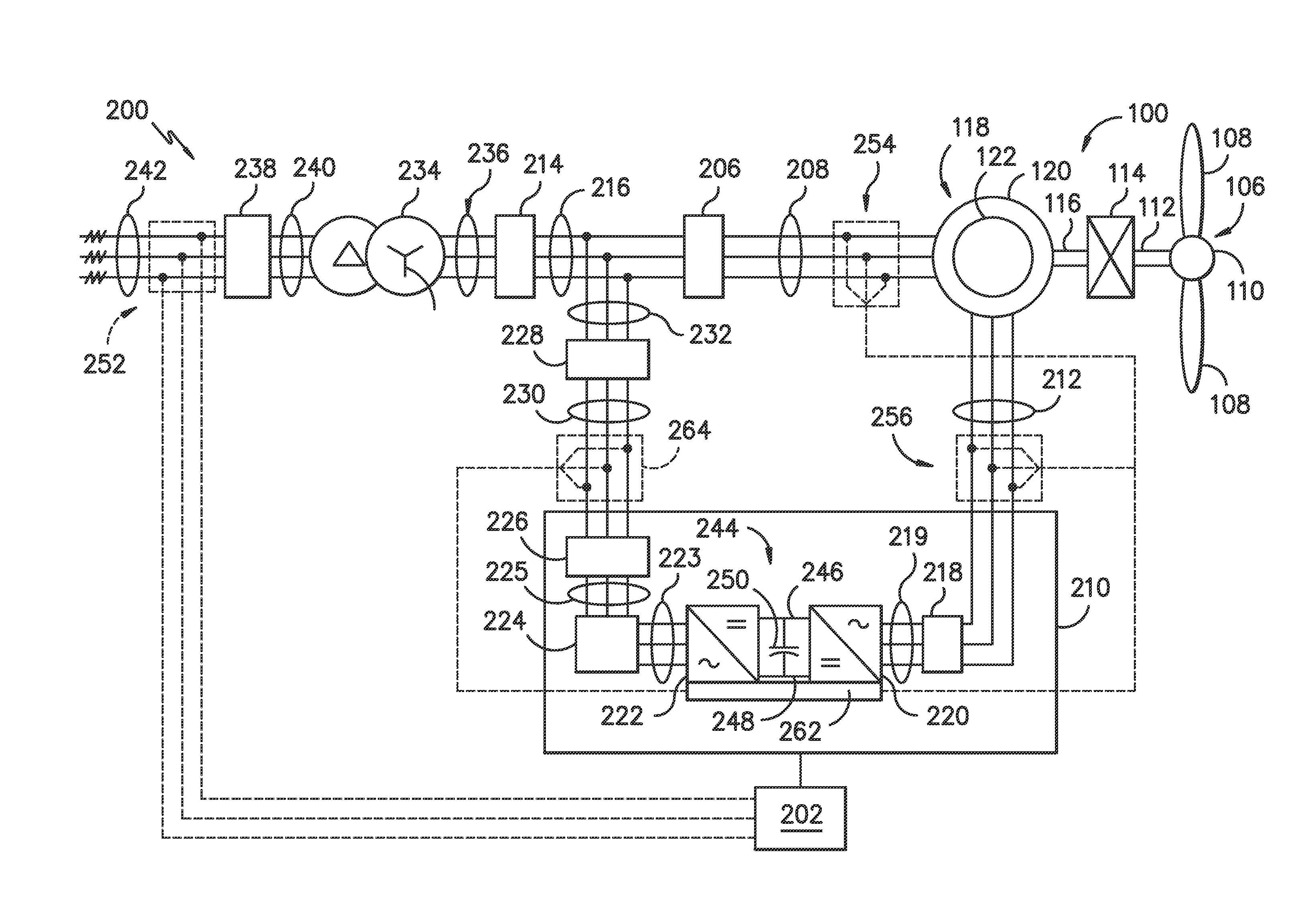
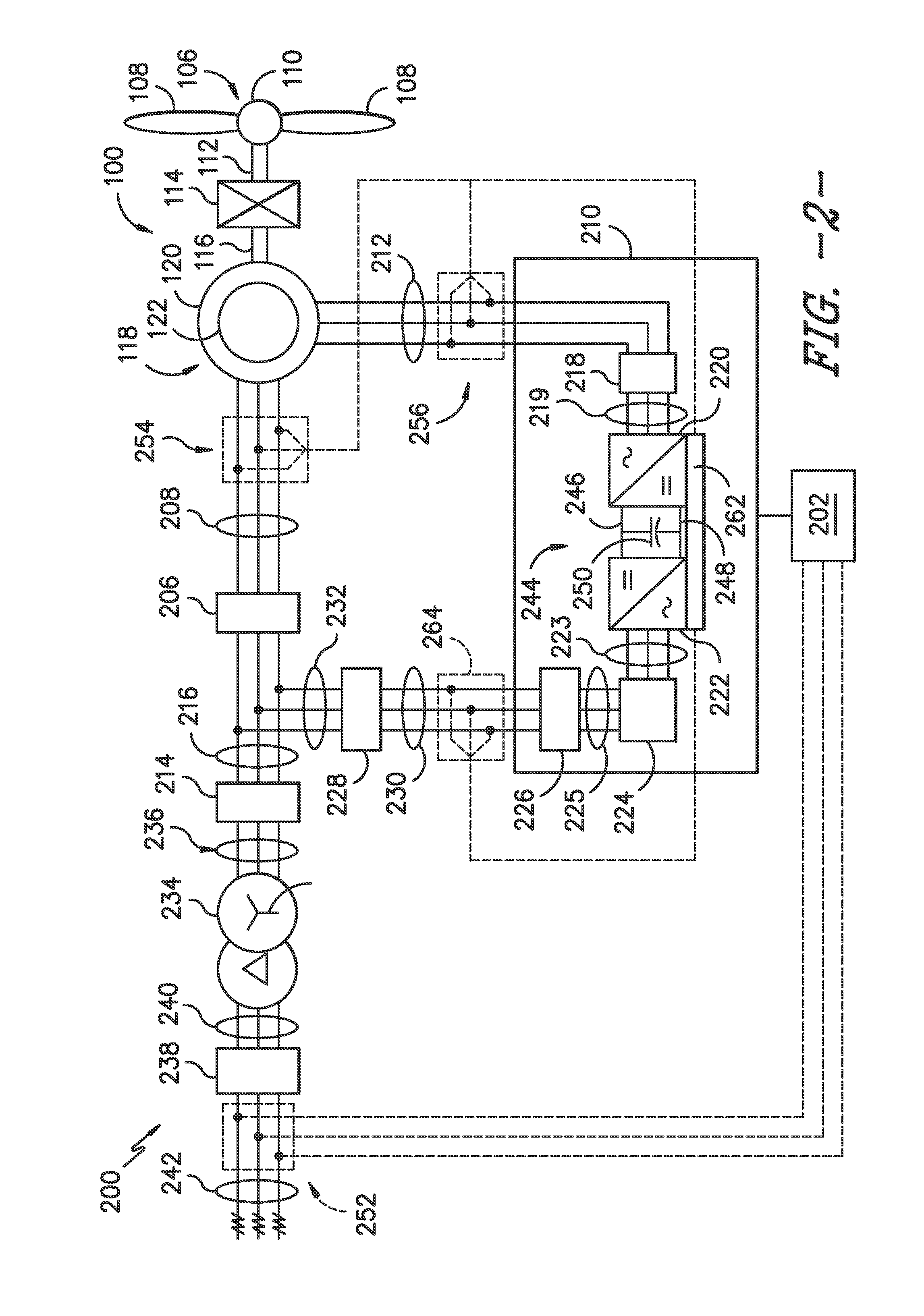
[0020]Generally, the present disclosure is directed to a system and method for optimizing wind turbine operation via a voltage regulator. For example, in various embodiments, the voltage regulator may be an on-line tap changer configured between the power g...


PUM


Abstract

The present disclosure is directed to a system and method for optimizing operation of a wind turbine. The method includes providing a voltage regulator between a power grid and the wind turbine. The voltage regulator is configured to control at least one voltage condition of the wind turbine. Another step includes monitoring, via one or more sensors, at least one operating condition and at least one voltage condition of the wind turbine. The method also includes comparing, via a controller, at least one of the operating condition or the voltage condition with a predetermined threshold to determine a margin-to-threshold ratio. Thus, a further step includes controlling the voltage regulator based on the comparison so as to maximize the margin-to-threshold ratio.

Description

FIELD OF THE INVENTION[0001]The present disclosure relates generally to wind turbines, and more particular to a system and method for optimizing wind turbine operation via a voltage regulator.BACKGROUND OF THE INVENTION[0002]Wind power is considered one of the cleanest, most environmentally friendly energy sources presently available, and wind turbines have gained increased attention in this regard. A modern wind turbine typically includes a tower, a generator, a gearbox, a nacelle, and a rotor having one or more rotor blades. The rotor blades transform wind energy into a mechanical rotational torque that drives one or more generators via the rotor. The generators are sometimes, but not always, rotationally coupled to the rotor through the gearbox. The gearbox steps up the inherently low rotational speed of the rotor for the generator to efficiently convert the rotational mechanical energy to electrical energy, which is fed into a utility grid via at least one electrical connection....

Claims


Application Information

Patent Timeline
Patent Type & Authority Applications(United States)
IPC IPC(8): H02P9/00F03D7/04F03D9/00
CPCH02P9/007F03D9/003H02J3/386G05F1/14F03D7/04H02J2300/28H02J3/381F03D9/255Y02E10/72Y02E10/76
Inventor HARDWICKE, JR., EDWARD, WAYNEHOLLIDAY, CORNELIUS, EDWARDBURRA, RAJNI, KANT
Owner GENERAL ELECTRIC CO
Why Eureka
Try Eureka