Method for Selective Display of Yarn in a Tufted Fabric with Offset Rows of Needles

a tufting machine and offset technology, applied in the field of tufting machines, can solve the problems of excessive yarn “wasted” on the back of the greige, maintenance of the tufting machine, and the production speed of those fabrics, so as to reduce the need for tacking stitches, reduce the cost of the tufting machine, and ensure the effect of uniformity

Active Publication Date: 2016-03-10
TUFTCO
View PDF15 Cites 10 Cited by
  • Summary
  • Abstract
  • Description
  • Claims
  • Application Information

AI Technical Summary

Benefits of technology

[0017]The present invention is addressed to techniques allowing a tufting machine to be threaded with at least two colors of yarn, and to display selected colors at any location on the face of the carpet, while burying other yarn colors, maintaining adequate face yarn density, and minimizing the tacking stitches necessary to hold loose yarns on the back of the backing fabric. Furthermore, such fabrics can be tufted on a tufting machine of conventional design and configuration so that the cost of the tufting machine is not prohibitive and the machine can also be used in the manufacture of many pre-existing fabric patterns.

Problems solved by technology

However, in the full color application described above, these efforts suffered from the difficulty that if a solid area of one color was to be displayed, only one of every four stitches was tufted to substantial height and the remaining three colors were “buried” by tufting the corresponding yarn bights to an extremely low height.
With only one of four stitches emerging to substantial height above the backing fabric without compensating by slowing the backing fabric feed, the resulting tufted fabric had inadequate face yarn for general acceptance and in any case excessive yarn was “wasted” on the back of the greige.
Such hollow needle, pneumatic tufting machines were traditionally most suitable for producing cut pile tufted fabrics and have been subject to limitations involving the sizes of fabrics that can be tufted, the production speed for those fabrics, and the maintenance of the tufting machines due to the mechanical complexity attendant to the machines' operation.
However, when attempts have been made to utilize a regular tufting machine configuration with a needle bar carrying a transverse row of needles in a similar fashion, the yarns are not selected for tufting and cut after tufting, but instead each yarn is tufted in every reciprocal cycle of the needle bar.
If several reciprocations are made as the needle bar moves laterally with respect to the backing fabric, then back stitch yarn for each of the colors of yarn is carried for each reciprocation and this results in considerable “waste” of yarn on the bottom of the resulting tufted fabric or greige.
It can be seen that this method, although functional, results in excess yarn on the bottom of the tufted fabric compared to ordinary tufted fabrics, and for a four-color thread-up requires that the tufting machine operate only at about one-fourth the speed that it would operate if tufting conventional fabric designs.
In this method of operation, there is again considerable excess yarn carried on the bottom of the backing fabric.
Although multiple cycles of lateral shifting presents some issues not present when shifting only a single lateral step, the principal issue is one of avoiding over-tufting or sewing exactly in the same puncture of the backing fabric made by a previous cycle of a nearby needle.
An additional problem presented by the first and second alternative techniques is the sheer number of penetrations of the backing fabric which results in degradation or slicing of nonwoven backing fabric materials that may be utilized in the manufacture of tufted fabrics for carpet tiles and special applications such as automotive carpets.
The necessity of shifting the rows of needles twice the gauge of the composite needle assembly results in patterns with less definition than could be obtained if it were possible to shift in increments of the composite gauge.
Although this allows the shifting of each row of needles in increments equal to the composite gauge, this solution was limited in by difficulties in creating cut and loop pile tufts from both the front needles and the rear needles.
A principal disadvantage to this tufting arrangement and operation is the requirement for the use of twice as many needles and twice as many single end yarn drives as would be the case with slower and less efficient tufting arrangements for the selective placement of individual yarns.
This results in increased cost and complexity of the tufting machine.

Method used


Image

  • Method for Selective Display of Yarn in a Tufted Fabric with Offset Rows of Needles
  • Method for Selective Display of Yarn in a Tufted Fabric with Offset Rows of Needles
  • Method for Selective Display of Yarn in a Tufted Fabric with Offset Rows of Needles

Examples


Embodiment Construction

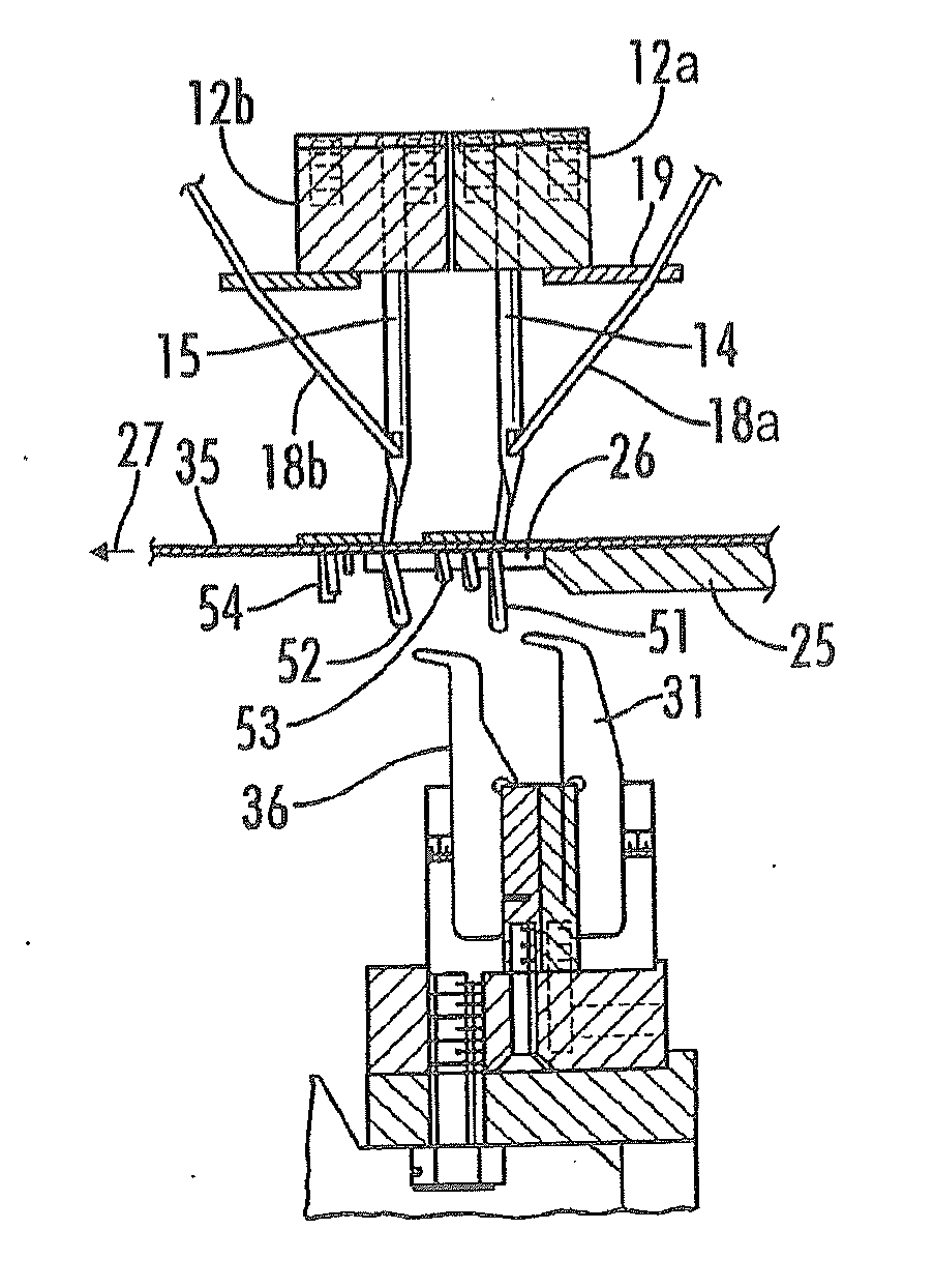
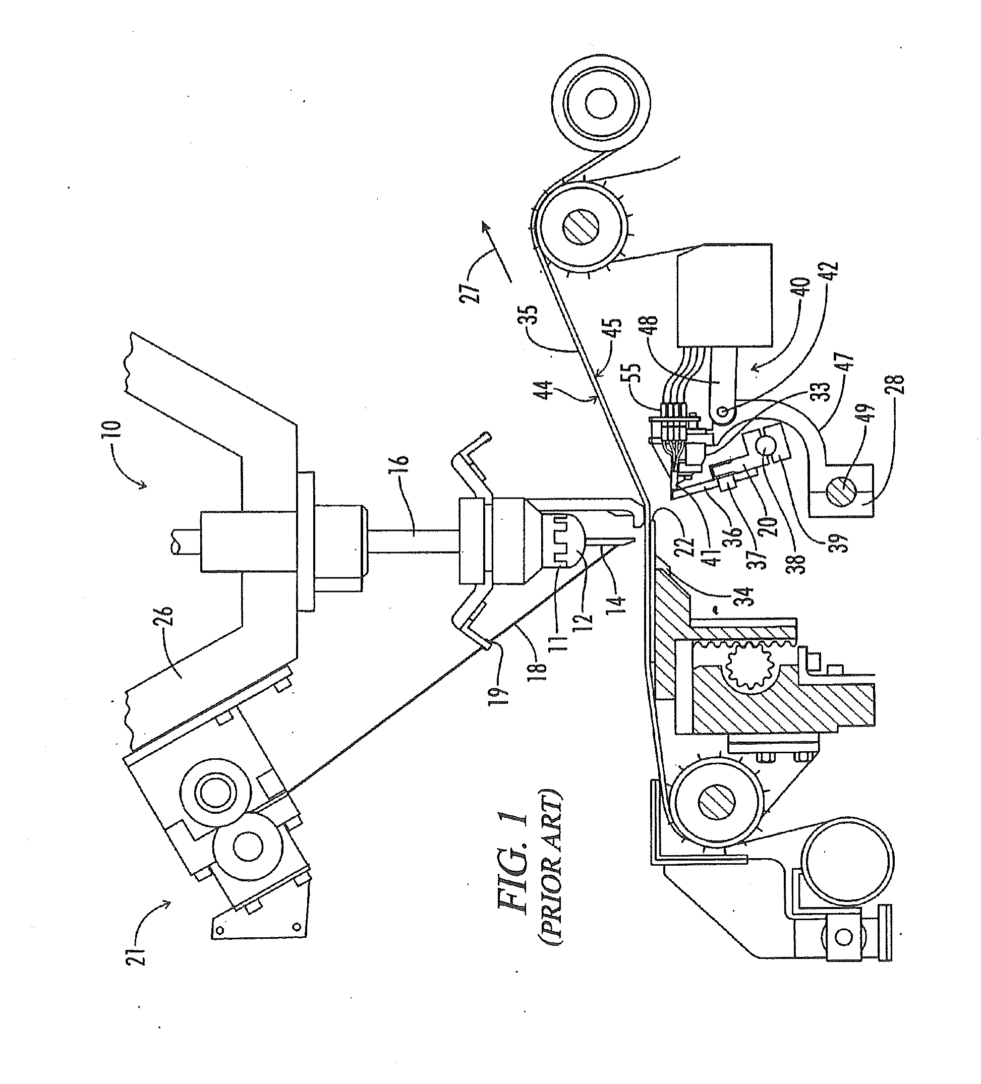
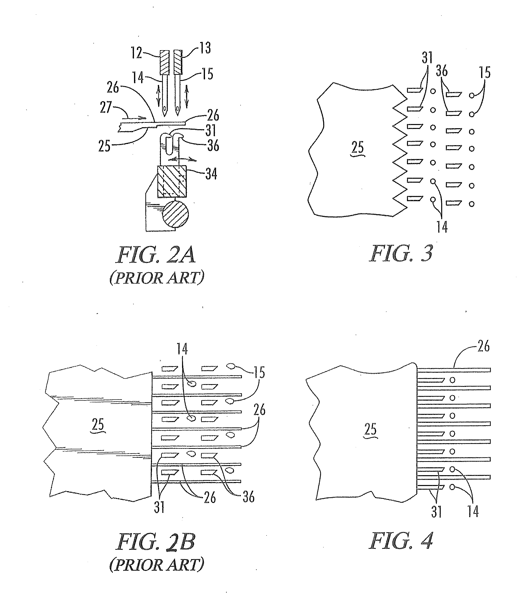
[0047]Referring now to the drawings in more detail, FIG. 1 discloses a multiple needle tufting machine 10 including an elongated transverse needle bar carrier 11 supporting a needle bar 12. The needle bar 12 supports a row of transversely spaced needles 14. The needle bar carrier 11 is connected to a plurality of push rods 16 adapted to be vertically reciprocated by conventional needle drive mechanism, not shown, within the upper housing 26.

[0048]Yarns 18 are supplied to the corresponding needles 14 through corresponding apertures in the yarn guide plate 19 from a yarn supply, not shown, such as yarn feed rolls, beams, creels, or other known yarn supply means, preferably passing through pattern yarn feed control 21. The yarn feed control 21 interfaces with a controller to feed yarns in accordance with pattern information and in synchronization with the needle drive, shifters, yarn seizing / cutting mechanisms and backing fabric feed.

[0049]The needle bar 12 may be fixedly mounted to th...


PUM


Abstract

A novel method of tufting carpets is provided to allow the use of the same sequence of colored yarns on front and rear staggered needle bars to yield sufficient gauge stitch density to provide for a solid appearance of any of the selected colors et, and utilizing optimized tacking of rear yarns to minimize loose yarn on the backing.

Description

[0001]The present application is a continuation-in-part of U.S. Ser. No. 14 / 151,801 filed Jan. 9, 2014 and which claims priority to U.S. Provisional Patent Application No. 61 / 750,755 filed Jan. 9, 2013.FIELD OF THE INVENTION[0002]The present invention relates to the operation of the tufting machines and is more particularly concerned with method for configuring and operating a tufting machine to economically produce a tufted fabric that displays selected yarns while concealing other yarns to produce novel carpet designs, without leaving long loops of unfastened yarns on the back of the greige.BACKGROUND OF THE INVENTION[0003]The tufting industry has long sought easy and efficient methods of producing new visual patterns on tufted fabrics. In particular, the industry has sought to tuft multiple colors so that any selected yarns of multiple colors could be made to appear in any desired location on the fabric. Significant progress toward the goal of creating carpets and tufted fabrics ...

Claims


Application Information

Patent Timeline
Patent Type & Authority Applications(United States)
IPC IPC(8): D05C15/20D05C15/30D05C15/32D05C15/34D05C15/36
CPCD05C15/20D05C15/30D05C15/36D05C15/34D05C15/32
Inventor FROST, STEVEN L.BISHOP, MIKELOVELADY, BRIAN K.BEATTY, PAUL E.MORGANTE, MICHAEL R.SMITH, JEFFREY D.DETTY, JASON DANIEL
Owner TUFTCO
Why Eureka
Try Eureka