Device and system for percussion rock drilling

a drilling device and a technology for percussion rock, applied in the direction of drilling pipes, drilling holes/well accessories, cutting machines, etc., can solve the problem of less stringent requirements for drilling bit support in the region of the most distal part of the drill head

Active Publication Date: 2016-03-10
EPIROC DRILLING TOOLS AB
View PDF4 Cites 6 Cited by
  • Summary
  • Abstract
  • Description
  • Claims
  • Application Information

AI Technical Summary

Problems solved by technology

It also renders the requirements regarding support of the drill bit at the region of the most distal part of the drill head ...

Method used


Image

  • Device and system for percussion rock drilling
  • Device and system for percussion rock drilling
  • Device and system for percussion rock drilling

Examples


Embodiment Construction

[0053]The invention will now be described in greater detail at the background of embodiments and with reference to the annexed drawings, wherein:

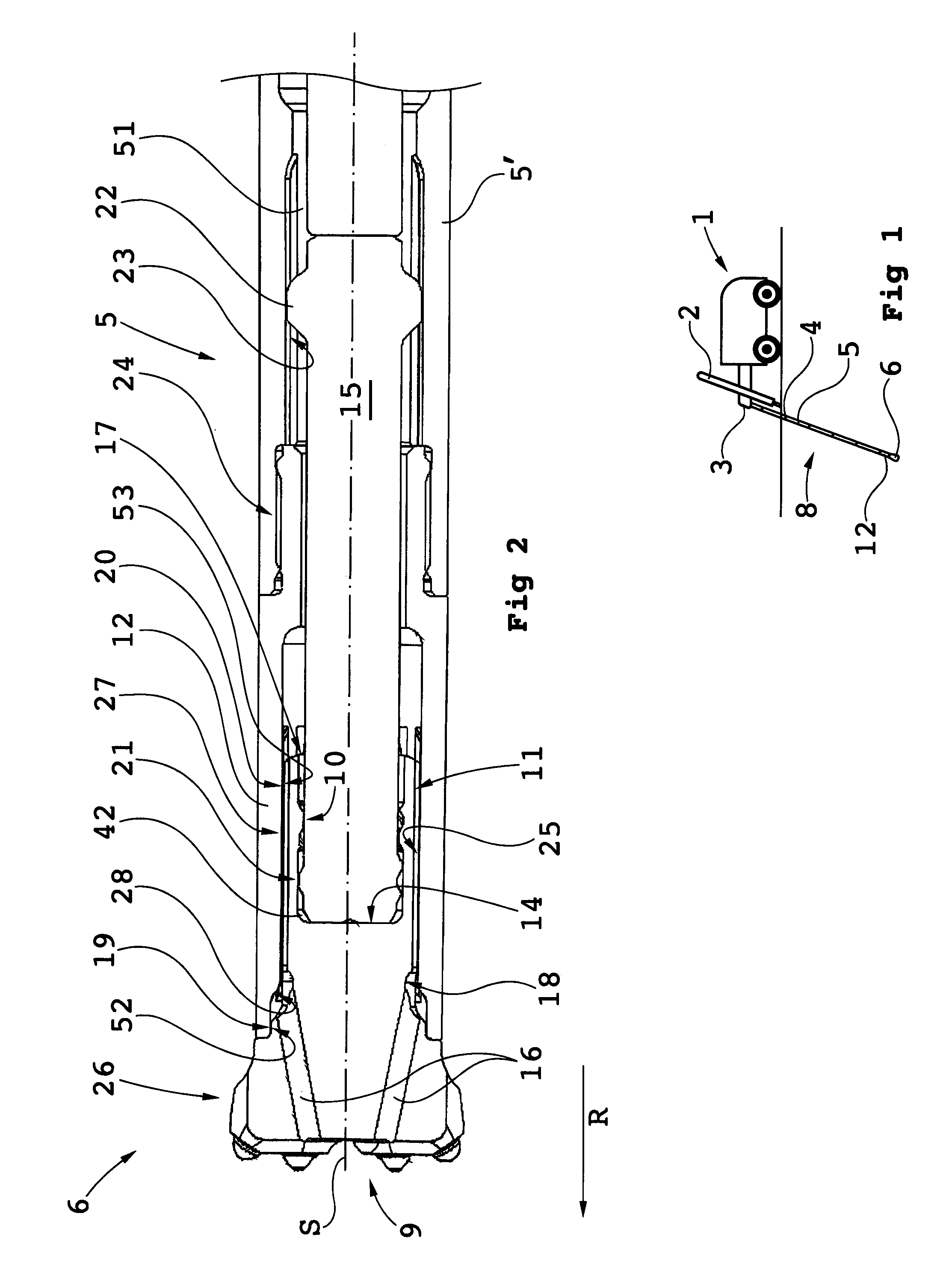
[0054]FIG. 1 diagrammatically shows a rock drilling rig and devices according to the invention,

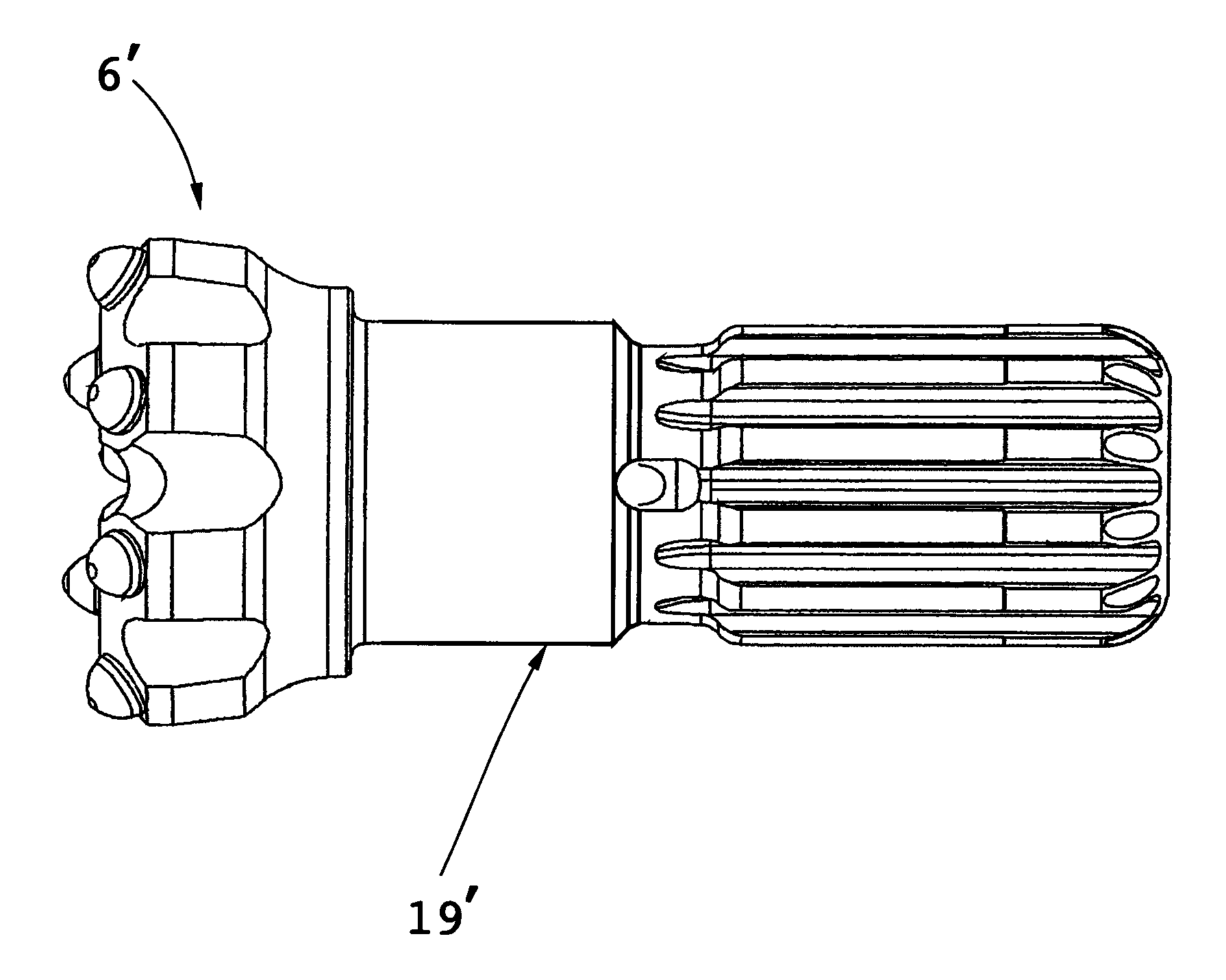
[0055]FIG. 2 in an axial section shows a first embodiment of a drill bit according to the invention,

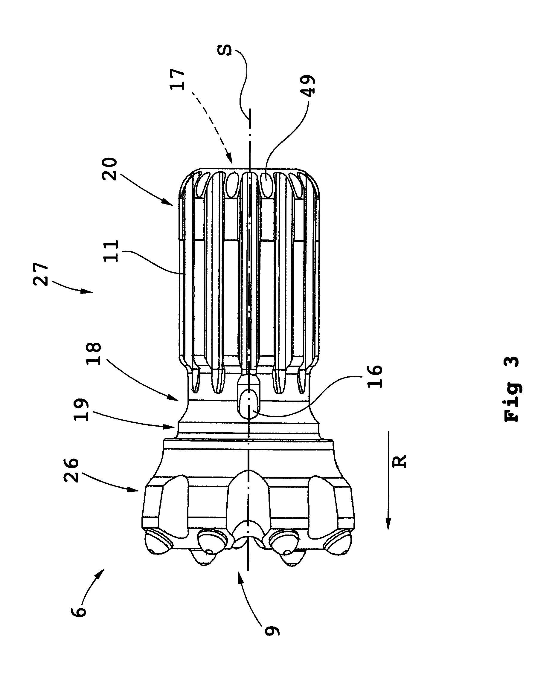
[0056]FIG. 3 shows the drill bit in FIG. 2 in a side view,

[0057]FIG. 4 shows a flex unit for use in a system according to the invention,

[0058]FIG. 5 shows, in a perspective view, a striker rod being part of an inventive drill string component,

[0059]FIG. 6 shows a section through a drill bit inside a drill head,

[0060]FIG. 7 shows diagrammatically a flow chart depicting a method sequence according to the invention, and

[0061]FIG. 8 shows in a side view a drill bit being a variant of the embodiment in FIG. 2.

DESCRIPTION OF EMBODIMENTS

[0062]In FIG. 1 is shown a rock drilling rig 1 having a feed beam 2 whereon a percussive top hammer rock drilling machine...


PUM


Abstract

A drill bit for percussion rock drilling. An impact portion includes an impact surface for striking against rock in an impact direction. An engagement portion includes a holder configured to hold the drill bit axially in a drill head of a drill string, and a rotation engagement member configured to connect the drill bit with the drill head for rotating the drill bit. An anvil surface is directed opposite to the impact direction for receiving shock waves from a striker rod of the drill string. A flushing channel is configured to transfer flushing fluid to the impact surface. The holder and the anvil surface are inside a holder recess having an opening that is directed opposite to the impact direction. Also a drill string component, a system and a method.

Description

FIELD OF THE INVENTION[0001]The invention relates to a drill bit for percussion rock drilling including an impact portion and an engagement portion. An anvil surface of the drill bit is directed opposite to the impact direction for receiving shock waves from a striker rod of the drill string.[0002]The invention also relates to a drill string component, a system and a method for rock drilling.BACKGROUND OF THE INVENTION[0003]A system for percussion rock drilling is previously known, wherein the individual drill string component includes a striker rod that transmits stress wave or shock wave energy and feed force from the drill rig and the rock drilling machine (hammer) to the drill bit. Basically, in a drill string including a plurality of drill string components of the type intended here, the striker rods make contact with each other and the shock wave propagates through the lengths of the striker rods and over the contact surfaces between the striker rods.[0004]The individual drill...

Claims


Application Information

Patent Timeline
IPC IPC(8): E21B1/00E21B10/38E21B17/03E21B17/22
CPCE21B1/00E21B10/38E21B17/22E21B17/03E21B4/06E21B4/14E21B10/36E21B1/02
Inventor CARLSSON, JIMMY
Owner EPIROC DRILLING TOOLS AB
Why Eureka
Try Eureka