

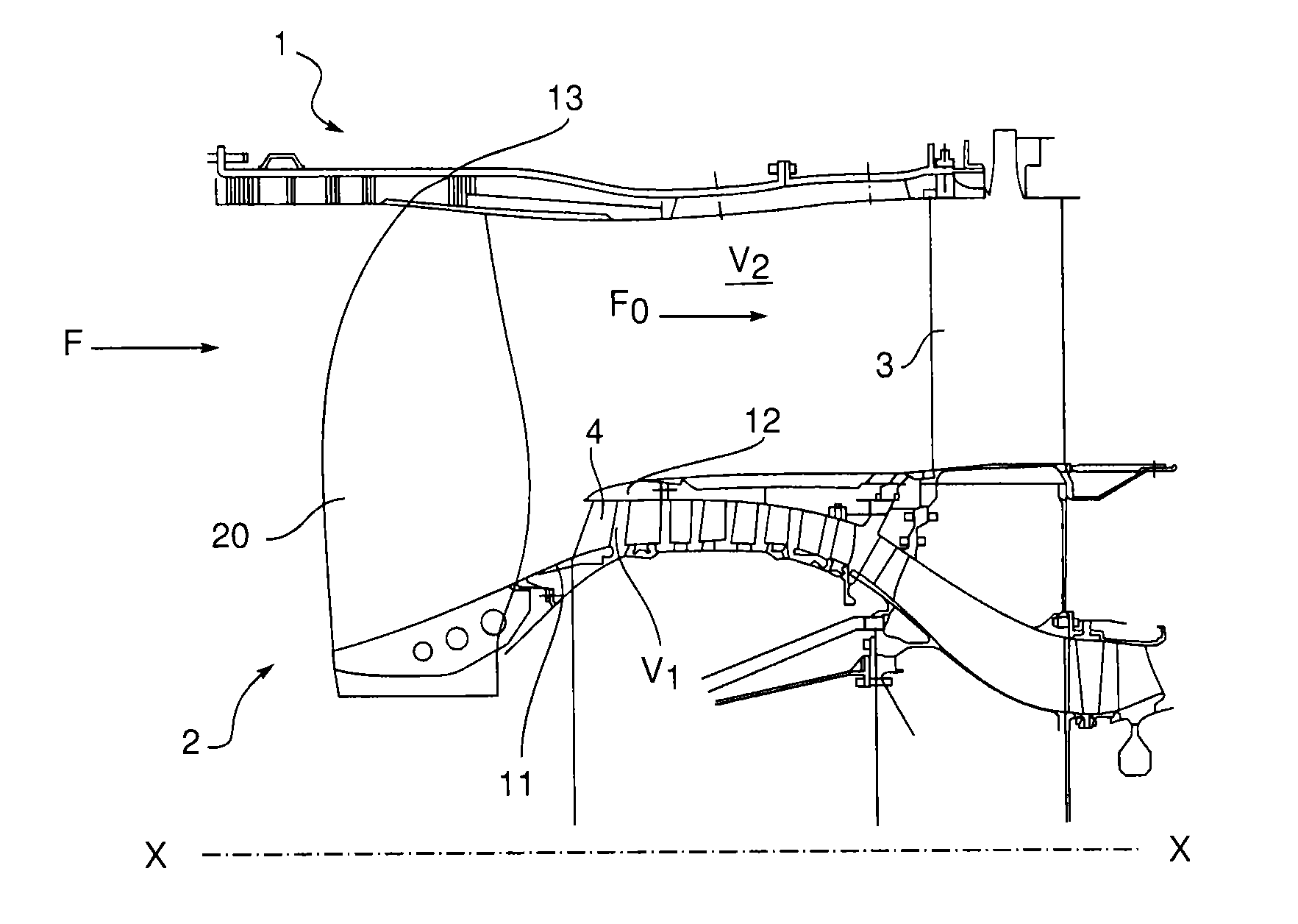
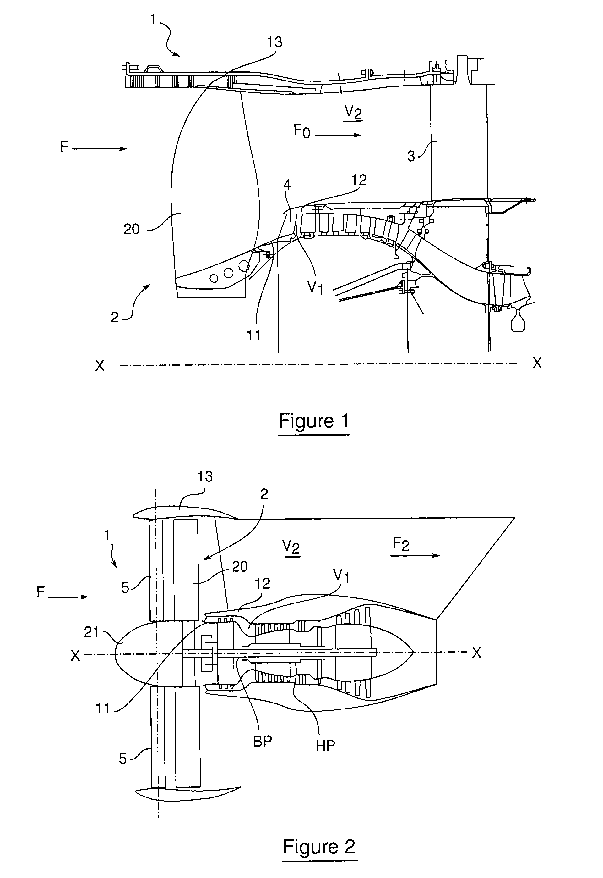
Turbomachine comprising a plurality of fixed radial blades mounted upstream of the fan
a technology of fixed radial blades and turbine engines, which is applied in the direction of machines/engines, sustainable transportation, mechanical devices, etc., can solve the problems of reducing compression efficiency, reducing the size and mass of thrust reversers, and causing major mass and drag
- Summary
- Abstract
- Description
- Claims
- Application Information
AI Technical Summary
Benefits of technology
Problems solved by technology
Method used
Image

Examples
first embodiment
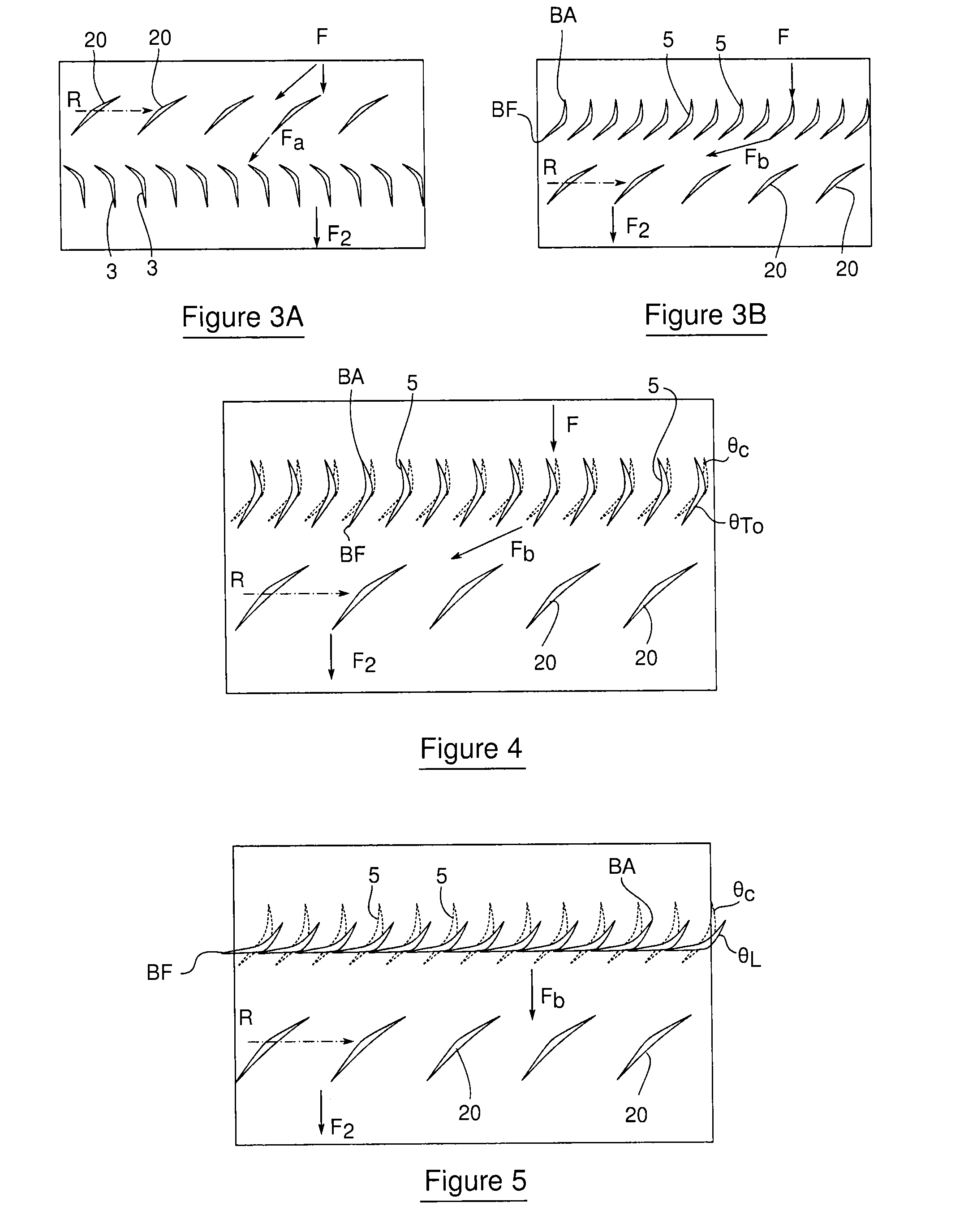
[0105] each radial stator vane 5 has an integral body which is movable in rotation about a radial axis (FIG. 7A). Therefore, depending on the operating state of the turbine engine 1, the entire radial stator vane 5 is oriented about its axis of extension in order to have a pitch in accordance with the cruising pitch angle θC, the take-off pitch angle θTO or the pitch angle when slowing down θL.
[0106]In this first embodiment, the means for variably setting the pitch of the radial stator vanes 5 are preferably located on one of the fixed structures, the outer casing 13 or the fixed axial cone 21, holding the vanes 5.
[0107]A preferred embodiment is described hereinafter in which said means are located on the outer casing 13, without excluding the possibility of them being located on the fixed axial cone 21.
[0108]With reference to FIG. 10, each radial stator vane 5 is mounted in rotation about a substantially radial pitch pin 23 on a pivot means 22 which is rigidly connected to the oute...
second embodiment
[0154]Moreover, in this second embodiment, each radial vane 5 is connected to the control rings 40, 41 by an assembly of two connecting rods 42 and 43 which are articulated to each other about a first and single hinge pin 44 for the substantially radial connecting-rod assembly.
[0155]The first connecting rod 42 is mounted, in the region of one of its ends, in rotation about a first substantially radial pivot pin 45 which is rigidly connected to the first control ring 24, and, in the region of its other end, in rotation about a second substantially radial pivot pin 46 which is rigidly connected to the second control ring 41.
[0156]For an average position of the two control rings 40, 41, the first connecting rod 42 is in this case substantially parallel to the longitudinal axis X-X and is offset in azimuth relative to the pitch pin 23 of the vane 5.
[0157]The second connecting rod 43 is mounted, close to its end opposite said first hinge pin 44, so as to pivot about a third pivot pin 33 ...
PUM
 Abstract
Description
Claims
Application Information