Holder for fastening a fuel distributor to an internal combustion engine

Active Publication Date: 2016-03-10
ROBERT BOSCH GMBH
View PDF10 Cites 0 Cited by
  • Summary
  • Abstract
  • Description
  • Claims
  • Application Information

AI Technical Summary

Benefits of technology

[0006]The retainer according to the present invention and the system of the present invention have the advantage that they permit improved v

Problems solved by technology

The engine assembly described in the published German Patent Application document DE 10 2010 046 344 A1 has the disadvantage that the insulation elements made of the elastomer material are secured by the head of the fastening element, which is screwed into the cam cover, via the spacer.
If, taking possible tolerances into consideration, the spacer is made somewhat too long, then high compression of the insulation elements results locally, which cannot be avoided because of the high tightening torque requi

Method used


Image

  • Holder for fastening a fuel distributor to an internal combustion engine
  • Holder for fastening a fuel distributor to an internal combustion engine
  • Holder for fastening a fuel distributor to an internal combustion engine

Examples


Embodiment Construction

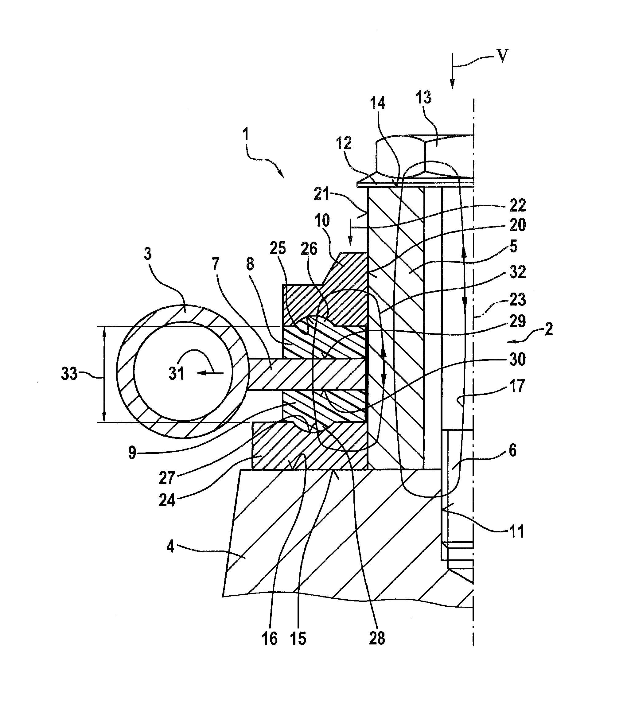
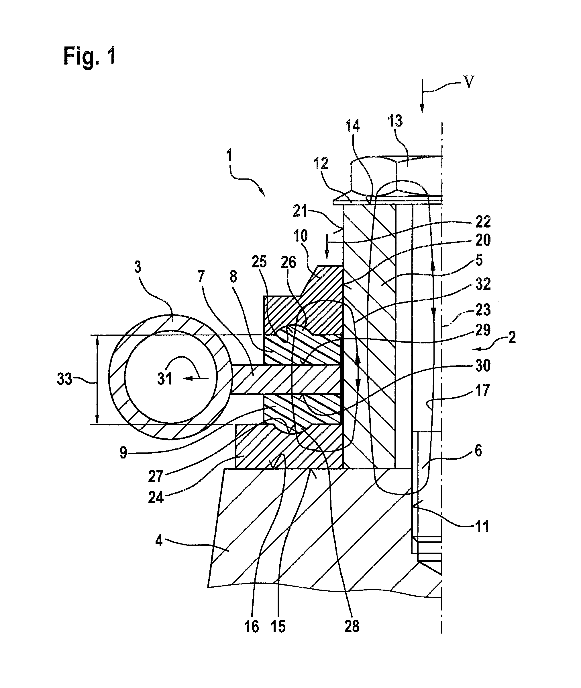
[0027]FIG. 1 shows a system 1 having a retainer 2 and a fuel distributor 3, especially a fuel distributor rail 3, and a portion of an internal combustion engine 4, especially a cylinder head 4, in a partial, schematic sectional view according to a first exemplary embodiment. System 1 is preferably a fuel-injection system 1 or a portion of a fuel-injection system 1.

[0028]Retainer 2 has a fastening body 5, a fastening means 6, a holding element 7, decoupling elements 8, 9, and a preloading element 10. Fastening means 6 is screwed into a threaded bore 11. A collar 12 of head 13, which takes the form of a screw head 13, abuts against an end face 14 of fastening body 5. In this manner, fastening body 5 is acted upon with its bottom side 15 against a surface 16 of internal combustion engine 4. The fastening force is generated here by a tightening torque of fastening means 6 in the form of fastening screw 6. In so doing, a force transmission adhesion comes about via fastening means 6 and f...


PUM


Abstract

A retainer for fastening a component, especially a fuel distributor, via a holding element to an internal combustion engine includes: decoupling elements, a fastening body and a fastening element. The fastening body is fastened to the internal combustion engine with the aid of the fastening element. In addition, the holding element is fastened to the fastening body via the decoupling elements. Moreover, a preloading element is provided that is joined to the fastening body, preloading of the decoupling elements being set by way of a predefined position of the preloading element relative to the fastening body in which the preloading element is joined to the fastening body.

Description

BACKGROUND OF THE INVENTION[0001]1. Field of the Invention[0002]The present invention relates to a retainer for fastening a component, especially a fuel distributor, to an internal combustion engine, as well as a system that preferably is a fuel-injection system or a part of a fuel-injection system. The invention relates especially to the domain of fuel-injection systems of internal combustion engines, where fuel under high pressure is injected into assigned combustion chambers of the internal combustion engine via fuel injectors.[0003]2. Description of the Related Art[0004]The published German Patent Application document DE 10 2010 046 344 A1 describes an engine assembly having a fuel rail. The engine assembly includes a cylinder head, a cam cover and a fuel-rail assembly. The fuel-rail assembly has the fuel rail, a clamp assembly and a fuel-injection device. The fuel rail of the engine assembly is attached to the cam cover. Meanwhile, the clamp assembly is secured to the fuel rail...

Claims


Application Information

Patent Timeline
IPC IPC(8): F02M63/02
CPCF02M63/0275F02M55/025F02F7/008F02M69/465F02M2200/09
Inventor REHWALD, ANDREASLANG, KLAUS
Owner ROBERT BOSCH GMBH
Why Eureka
Try Eureka