
Translational tuned mass damper with continuously adjustable damping characteristics for application to high speed wind tunnel testing

a technology of tuned mass and damping characteristics, applied in the direction of shock absorbers, instruments, mechanical equipment, etc., can solve the problems of increasing the chance of scale effects in the wind tunnel data, introducing experimental artifacts, and affecting the accuracy of wind tunnel data

Active Publication Date: 2016-03-10
THE BOEING CO
View PDF13 Cites 13 Cited by
  • Summary
  • Abstract
  • Description
  • Claims
  • Application Information

AI Technical Summary

Benefits of technology

The patent text describes a solution to the problem of unwanted vibrations and artifacts in wind tunnel data. One solution is to reduce the dynamic pressure of the wind tunnel, but this also reduces the speed of the wind tunnel. Another solution is to increase the stiffness of the support structure, but this can decrease sensitivity and make the model less realistic. The third solution is to avoid test conditions that can cause unsteady aerodynamic phenomena, but this can result in missed test opportunities. The patent describes a mass-damping apparatus that can be coupled to a wind tunnel model to damp vibrations and reduce unwanted phenomena. The apparatus can be adjusted to match the natural vibration frequencies of the support structure or the model, and the damping coefficient can be adjusted continuously to achieve optimal damping at any given frequency. This allows for expanded testing over a range of angles and speeds, potentially saving several test flights per program.

Problems solved by technology

An inherent complication of wind tunnel testing is the introduction of experimental artifacts that would not be present in a real-world setting.
These forces would obviously not be present on a real-world aircraft, and can interfere with any efforts to measure the forces on the model that arise from the aerodynamic performance of the model itself.
This solution has the disadvantage of increasing the chance of scale effects in the wind tunnel data.
However, increasing the balance capacity would tend to decrease the sensitivity of the tests, and increasing the size of the support would take the model farther away from the reality it is trying to replicate, both undesirable effects.
In either case, the degree of damping may be difficult or impossible to adjust, at least without significant disassembly of the damper.
For example, in mass dampers that use oil as a damping medium, to change the damping coefficient one must change the kind of oil being used, a potentially messy and time-consuming process.
As a result, it may not always be possible, or at least practical, to achieve optimal damping, particularly if the damper is designed to have a variable natural frequency.
In addition, friction-based dampers can experience undesirable wear at the frictional surfaces, and viscous dampers can develop leaks that affect the damping force and can damage the damper's surroundings.

Method used


Image

  • Translational tuned mass damper with continuously adjustable damping characteristics for application to high speed wind tunnel testing
  • Translational tuned mass damper with continuously adjustable damping characteristics for application to high speed wind tunnel testing
  • Translational tuned mass damper with continuously adjustable damping characteristics for application to high speed wind tunnel testing

Examples


Embodiment Construction

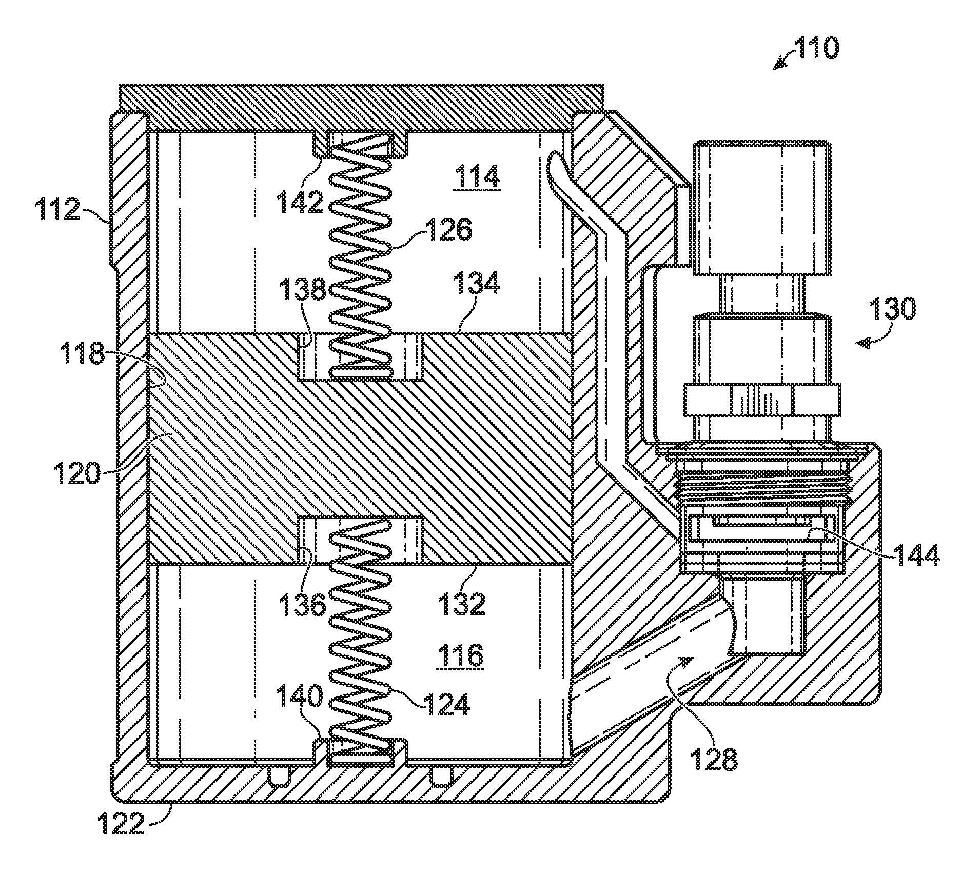
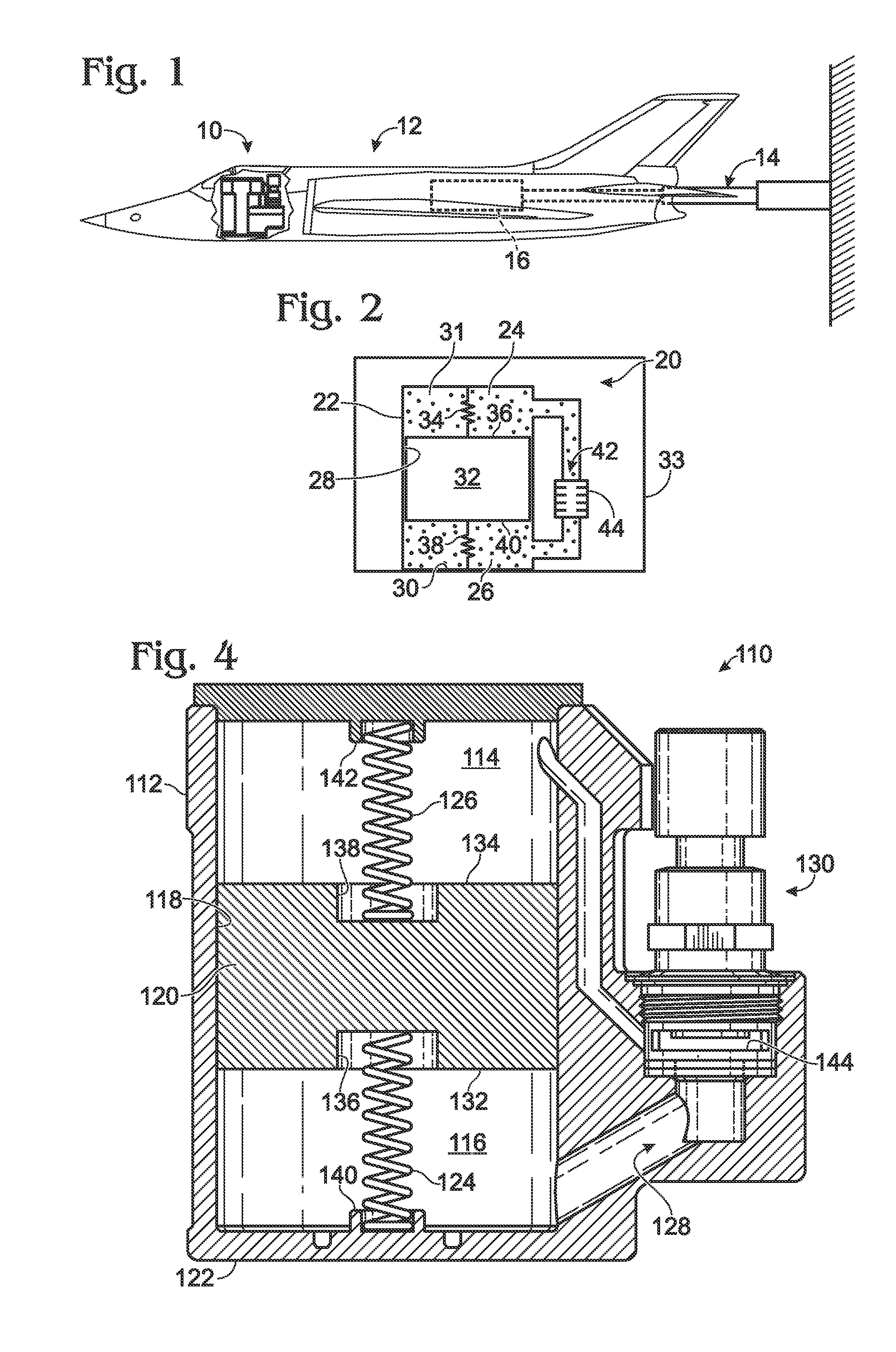
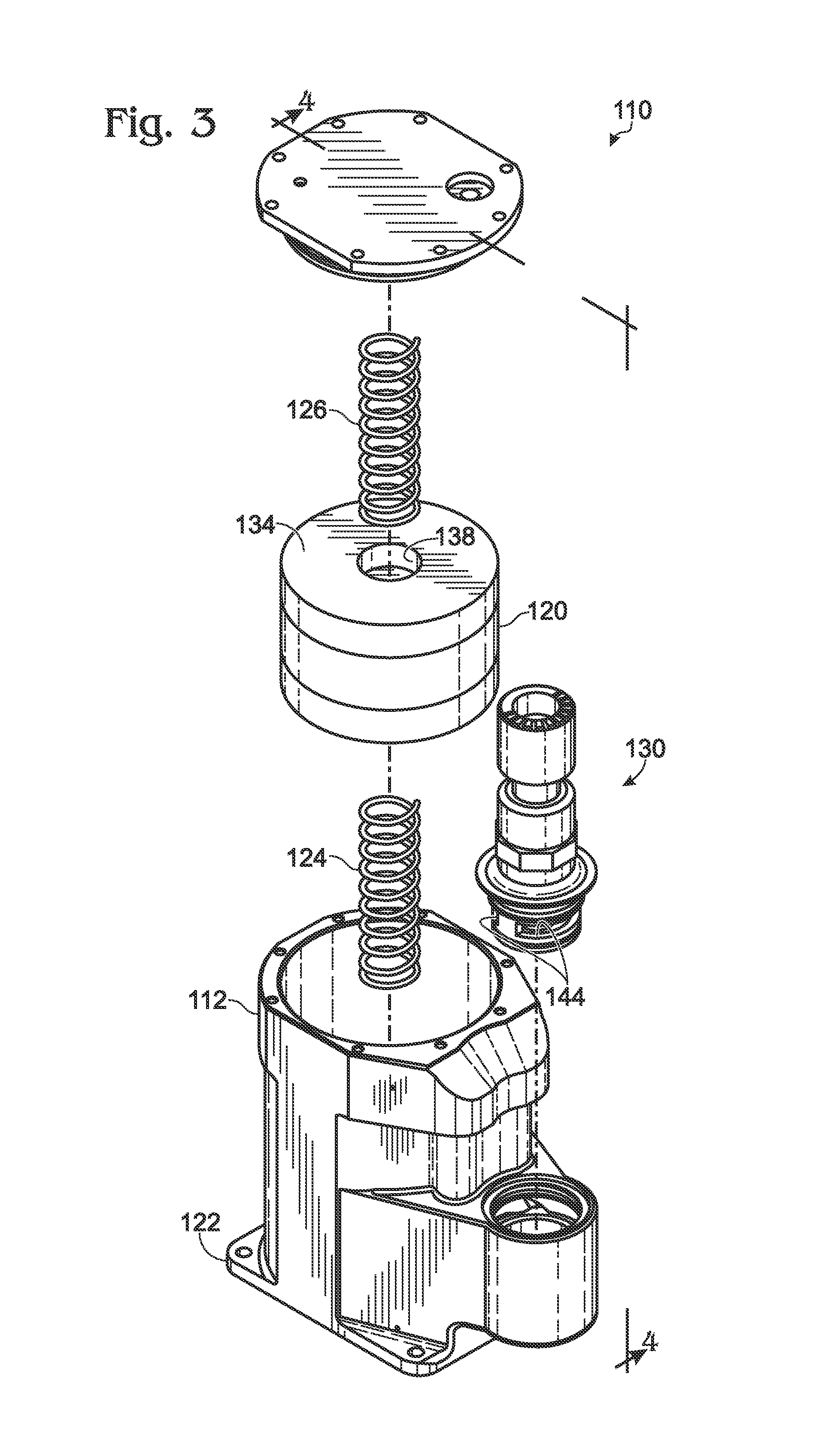
[0016]The present disclosure generally relates to a mass damper that may be coupled to a scale model airplane or other object, typically during wind tunnel testing, to help prevent undesirable vibrations of the model at various natural frequencies of the testing system. More specifically, the present teachings relate to mass dampers that may include a mass configured to move between two pressure chambers, and a fluid passageway connecting the two chambers. In some cases, airflow (or fluid flow) through the passageway may be controlled by an adjustable valve, providing a degree of adjustability not found in previously known mass dampers. Methods and apparatus according to the present teachings may be particularly suitable for use in high speed wind tunnel testing, where dynamic pressure reaches 25 pounds per square foot or more.

[0017]FIGS. 1-4 depict various aspects and embodiments of mass dampers according to the present teachings. FIG. 1 is semi-transparent side elevational view de...


PUM


Abstract

A system, including methods and apparatus, of tuning a mass-damping apparatus to reduce dynamics forces on a wind tunnel model during wind tunnel testing. The mass-damping apparatus is coupled to a wind tunnel model and may comprise first and second pressure chambers containing a gas, a mass configured to move back and forth between the pressure chambers in a substantially airtight manner and thereby to alter gas pressure within each pressure chamber, at least one spring configured to exert a position-dependent force upon the mass, and a passageway configured to allow the gas to pass between the chambers.

Description

INTRODUCTION[0001]Aerodynamic testing of models in wind tunnels is a common and important part of the aeronautics industry. Accurate testing is necessary for safety, and can potentially save millions of dollars by eliminating real-world test flights. An inherent complication of wind tunnel testing is the introduction of experimental artifacts that would not be present in a real-world setting. Such artifacts include the forces exerted on a model during testing that arise from the support structure that is holding the model in place. These forces would obviously not be present on a real-world aircraft, and can interfere with any efforts to measure the forces on the model that arise from the aerodynamic performance of the model itself.[0002]One solution to the problem of undesirable artifact forces is to reduce the dynamic pressure of the wind tunnel and hence the wind speed. This solution has the disadvantage of increasing the chance of scale effects in the wind tunnel data. A second ...

Claims


Application Information

Patent Timeline
Patent Type & Authority Applications(United States)
IPC IPC(8): F16F15/02F16F7/104
CPCF16F15/022F16F7/104F16F7/116G01M9/04F16F7/112F16F7/1005F16F9/34
Inventor MCGRANAHAN, BRYAN DAVIDRUEGER, MATHEW LEE
Owner THE BOEING CO
Learn More