Hardware and method for implementation of in situ acoustic thermograph inspections

Inactive Publication Date: 2016-03-10
SIEMENS ENERGY INC
View PDF6 Cites 5 Cited by
  • Summary
  • Abstract
  • Description
  • Claims
  • Application Information

AI Technical Summary

Problems solved by technology

This technique is disadvantageous, however, because it is inspector intensive and dependent and requires the person to be skilled.
This technique has the drawback that it is also very operator intensive, slow and tedious.
Although this technique has been successful for detecting disbands and corrosion, it is ordinarily not successful at detecting vertical cracks

Method used


Image

  • Hardware and method for implementation of in situ acoustic thermograph inspections
  • Hardware and method for implementation of in situ acoustic thermograph inspections
  • Hardware and method for implementation of in situ acoustic thermograph inspections

Examples


Embodiment Construction

[0018]The following discussion of the embodiments of the invention directed to a system and method for performing in situ acoustic thermograph inspection is merely exemplary in nature, and is in no way intended to limit the invention or its applications or uses. For example, while in situ thermograph inspection of turbine blades in a steam turbine are described herein, other types of in situ acoustic thermograph inspection may be used according to the system and method of the present invention.

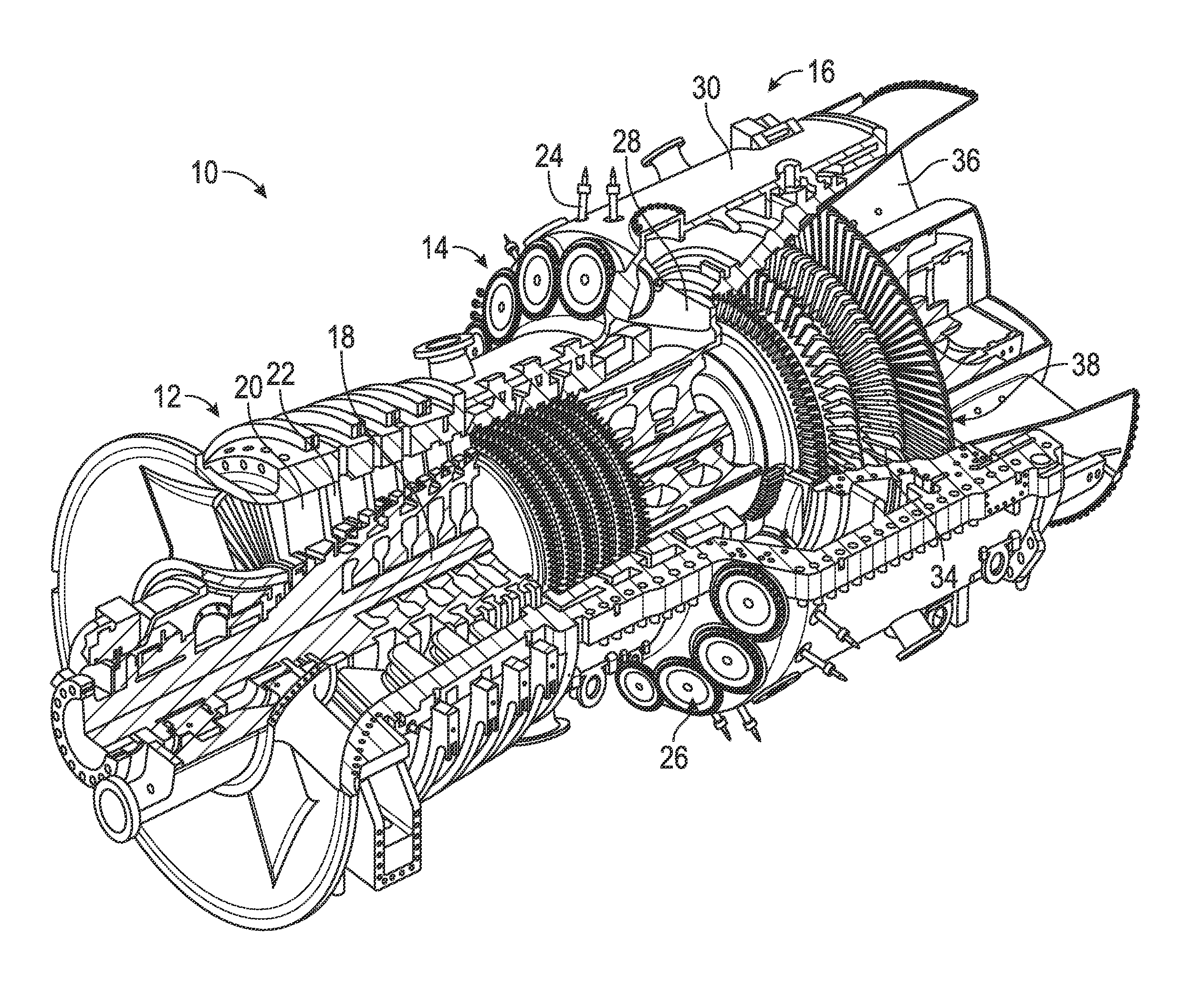
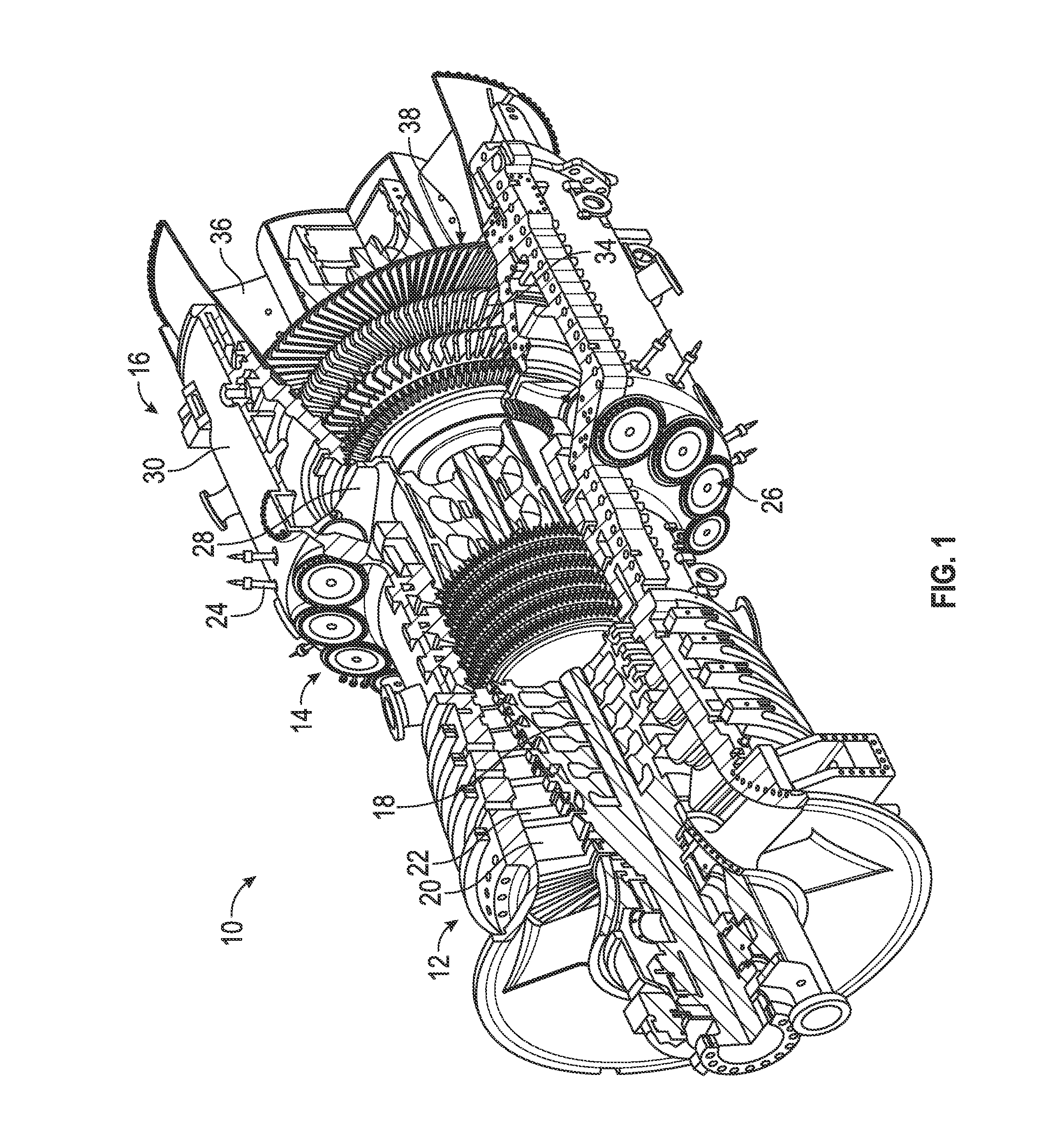
[0019]FIG. 1 is a cut-away, isometric view of a gas turbine engine 10 including a compressor section 12, a combustion section 14 and a turbine section 16 all enclosed within an outer housing 30, where operation of the engine 10 causes a central shaft or rotor 18 to rotate, thus creating mechanical work. The engine 10 is illustrated and described by way of a non-limiting example to give context to the invention discussed below. Those skilled in the art will appreciate that other gas turbine eng...


PUM


Abstract

A system and method include an acoustic thermography stack and a frame that the stack is slidably mounted to. The frame includes an end frame portion with a blade stop, and an air cylinder provides force to move the stack up and down a rail of the frame such that a turbine blade may be clamped between a cap of the stack and the blade stop. The clamped blade is excited using the stack, and an infrared camera is used to detect critical indications in the blade.

Description

BACKGROUND OF THE INVENTION[0001]1. Field of the Invention[0002]This invention relates generally to a system and method for performing thermograph inspection of turbine blades and, more particularly, to a system and method for performing acoustic thermograph inspection of turbine blades without removing the blades from the turbine so as to eliminate the need for costly blade removal to perform the inspection.[0003]2. Discussion of the Related Art[0004]The world's energy needs continue to rise which provides a demand for reliable, affordable, efficient and environmentally-compatible power generation. A turbine engine is one known machine that provides efficient power, and often has application for an electric generator in a power plant, or engines in an aircraft or a ship. A typical gas turbine engine includes a compressor section, a combustion section and a turbine section. The compressor section provides a compressed air flow to the combustion section where the air is mixed with a ...

Claims


Application Information

Patent Timeline
IPC IPC(8): G01N25/72F01D21/00
CPCF01D21/003G01N25/72F01D25/285F05D2260/83F05D2270/80
Inventor RUHGE, FORREST R.HATCHER, JR., CLIFFORDDEASCANIS, JOSHUAWILLIAMS, JAMES P.SHANNON, ROBERT G.
Owner SIEMENS ENERGY INC
Why Eureka
Try Eureka