This helps you quickly interpret patents by identifying the three key elements:
Problems solved by technology
Method used
Benefits of technology
Benefits of technology
The present invention introduces a new pump that can overcome the limitations and drawbacks of conventional pumps. It does this by using a membrane that moves back and forth to act as a valve during both the suction and dispensing steps. This allows for smoother and more efficient pumping.
Problems solved by technology
The dispensing pumps known in the art are thus rather complicated to produce, since there is a large number of component parts to be assembled.
Furthermore, the dispensing pumps known in the art are particularly subject to malfunction problems that may occur during either the suction or the dispensing step.
In particular, the two valves that place the suction / compression chamber in communication with the suction duct and the dispenser duct, respectively, are particularly sensitive components, in fact they can easily be damaged, thus preventing the fluid from being drawn from the container or dispensed towards the outside.
The main problems posed by the valves contained in a dispensing pump are due to their movable parts, which are the most sensitive and most subject to damage.
Another limitation of the dispensing pumps known in the art lies in that, when the pump is mounted on the container in which the fluid is held, the hollow body that defines the suction / compression chamber is situated inside the container.
The position of the suction / compression chamber poses considerable technical limitations to the design of a dispensing pump.
First of all, the presence of the chamber inside the container causes a reduction of the useful volume enclosed by the container.
Furthermore, as the suction / compression chamber must be introduced in the container through the neck of the latter, its size is limited by the size of the container's neck.
Method used
Image
Click on the blue label to locate the original text in one second.
Reading with bidirectional positioning of images and text.
Examples
first embodiment
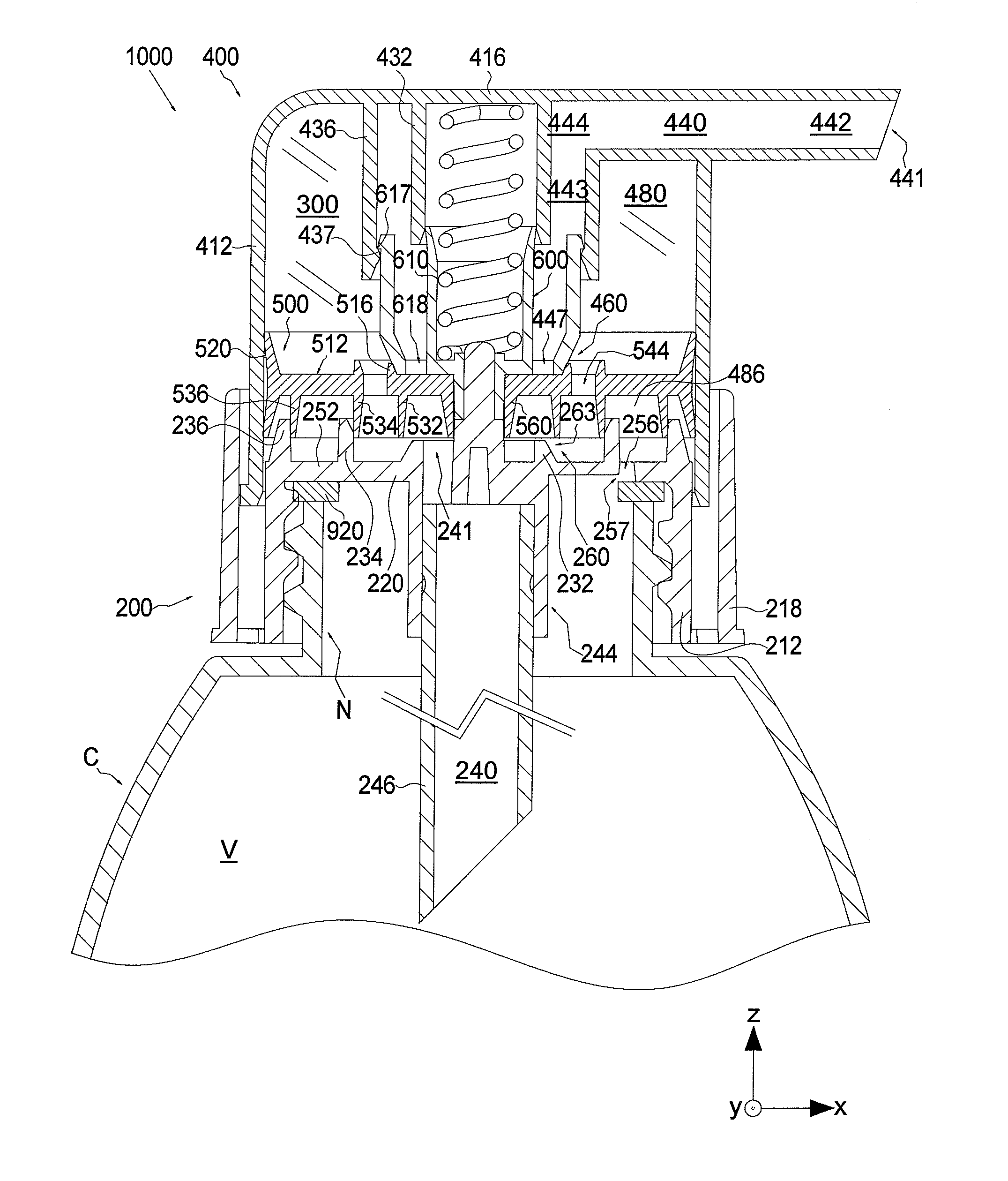
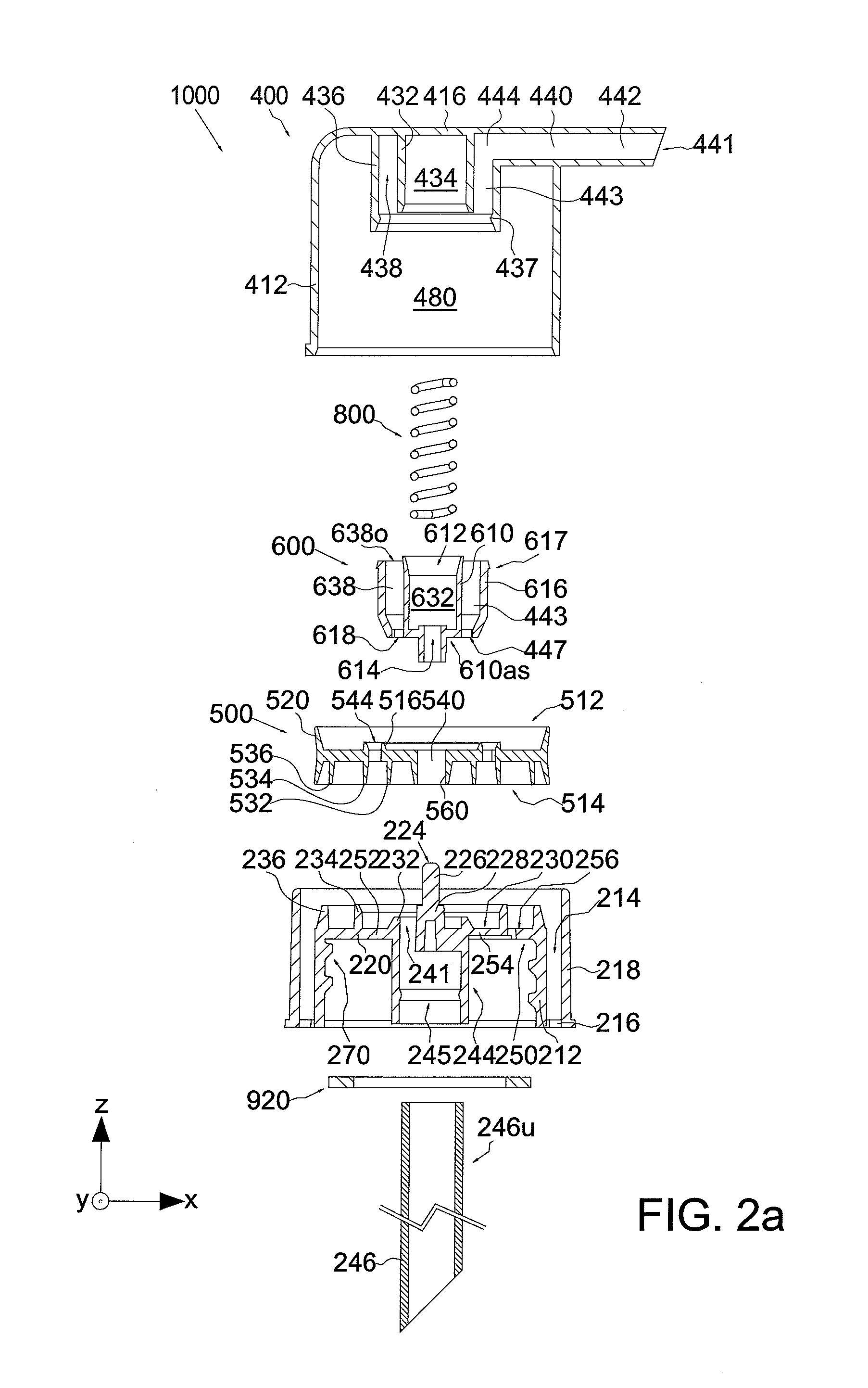
[0064]Figures from 2a to 2f schematically illustrate the dispensing device 1000 according to the present invention.
[0065]FIG. 2a shows an exploded view of the pump 1000 according to the first embodiment of the invention, in which the component parts can be individually recognized. FIG. 2b, instead, shows the pump 1000 fixed to a container C in a rest position, ready for the dispensing step.
[0066]The dispensing device 1000 comprises an actuator element 400, a union element 600, a membrane 500 and a connection element 200 that are described in detail below. Furthermore, the dispensing device 1000 comprises a dispenser duct 460 and a suction duct 260. The dispensing device 1000 may also comprise an elastic element 800 and a gasket 920.
[0067]As shown in FIG. 2b, the actuator element 400, the connection element 200 and the membrane 500 define a cavity in which the fluid suction / compression chamber 300 is obtained. The suction / compression chamber 300 can alternatively be placed in communi...
second embodiment
[0131]Figures from 3a to 3f schematically show the pump 1000 according to the present invention.
[0132]The second embodiment of the invention differs from the first embodiment substantially for the actuator element. All the other component parts have the same shape and functions as the corresponding parts of the pump 1000 according to the first embodiment of the invention. It is understood that, if not specified otherwise, the description of similar or identical component parts provided with reference to the first embodiment of the invention can be applied to the second embodiment of the invention.
[0133]With particular reference to FIGS. 3a and 3b, the actuator element 400 comprises an upper portion 452 and a lower portion 454, suited to be rigidly fixed to each other.
[0134]The upper portion 452 comprises a top wall 416, suited to be connected to a side annular wall 412 belonging to the lower portion 454. The upper portion 452 comprises also a wall 435 that develops in the vertical d...
third embodiment
[0149]Figures from 4a to 4f schematically show the pump 1000 according to the present invention.
[0150]The pump 1000 according to the third embodiment of the invention differs from the first embodiment essentially for the arrangement of the suction / compression chamber. Only the differences between the third and the first embodiment of the invention are described here below. It is understood that, if not expressly specified otherwise, the description of analogous or identical component parts provided with reference to the first embodiment of the invention applies also to the third embodiment of the invention.
[0151]The actuator element 400, the elastic element 800, the union element 60 and the membrane 500 of the pump 1000 according to the third embodiment of the invention have a structure that is similar or identical to the structure of the corresponding parts of the pump according to the first embodiment of the invention.
[0152]The connection element 200 of the pump 1000 comprises a s...
PUM
Abstract
The invention is a fluid dispensing device suited to be connected, by means of a connection element (220), to a container (C) holding the fluid that can be dispensed from the inside to the outside of the container through an actuator element (400), comprising: a suction duct (240) suited to communicate with the fluid held inside the container (C), a dispenser duct (440) in communication with the outer space with respect to the volume (V) enclosed by the container (C), a suction / compression chamber (300) that can communicate with the suction duct (240) and the dispenser duct (440), a suction valve (260) suited to alternatively allow and prevent the passage of a fluid between the suction duct (240) and the suction / compression chamber (300) when, respectively, the suction valve is closed and open, a dispensing valve (460) suited to alternatively allow and prevent the passage of a fluid between the dispenser duct (440) and the suction / compression chamber (300) when, respectively, the suction valve is closed and open, a tight membrane (500) slidingly coupled with the walls of the suction / compression chamber (300) so that it can be translated in a predetermined direction; both the suction valve (260) and the dispensing valve (460) comprise the membrane (500). The invention concerns also a system for containing and dispensing fluids (F).
Description
FIELD OF APPLICATION OF THE INVENTION[0001]The invention concerns devices for pumping and dispensing fluids. In greater detail, the present invention concerns a pumping device suited to dispense fluids that are held in a container and suited to be coupled with the neck of the container. The present invention is particularly effective for pumping and dispensing fluid foods, liquid detergents, creams, perfumes and similar substances.DESCRIPTION OF THE STATE OF THE ART[0002]In the state of the art there are various types of pumps for fluids stored inside a container.[0003]The dispensing pumps of the known type are generally constituted by a suction / compression chamber defined by a hollow body and suited to draw / compress the fluid to be dispensed. The suction / compression chamber communicates with a suction duct that draws the fluid from a container and a dispenser duct that conveys the fluid towards the outside. A first valve is positioned in the pump in such a way as to alternatively c...
Claims
Application Information
Patent Timeline
Application Date:The date an application was filed.
Publication Date:The date a patent or application was officially published.
First Publication Date:The earliest publication date of a patent with the same application number.
Issue Date:Publication date of the patent grant document.
PCT Entry Date:The Entry date of PCT National Phase.
Estimated Expiry Date:The statutory expiry date of a patent right according to the Patent Law, and it is the longest term of protection that the patent right can achieve without the termination of the patent right due to other reasons(Term extension factor has been taken into account ).
Invalid Date:Actual expiry date is based on effective date or publication date of legal transaction data of invalid patent.

