Microelectromechanical microphone

a micro-electromechanical and microphone technology, applied in the direction of microphone structure association, semiconductor electrostatic transducer, instruments, etc., can solve the problem of difficult integration of two chips, such as a control asic and a micro-electromechanical transducer, in the packag

Active Publication Date: 2019-03-05
STMICROELECTRONICS MALTA +1
View PDF22 Cites 5 Cited by
  • Summary
  • Abstract
  • Description
  • Claims
  • Application Information

AI Technical Summary

Benefits of technology

[0010]One or more embodiments of the present disclosure provide a microelectromechanical microphone that may overcome or at least attenuate one or more of the limitations described above.

Problems solved by technology

The at times tumultuous development of products of this kind may, in some cases, set down specifications that are contrasting or difficult to reconcile.
Additionally, fitting two chips, such as a control ASIC and a microelectromechanical transducers in the package can be difficult.

Method used


Image

  • Microelectromechanical microphone
  • Microelectromechanical microphone
  • Microelectromechanical microphone

Examples


Embodiment Construction

[0115]Features described herein that have same reference numbers have the same structure and function and thus may not be described again in the interest of brevity.

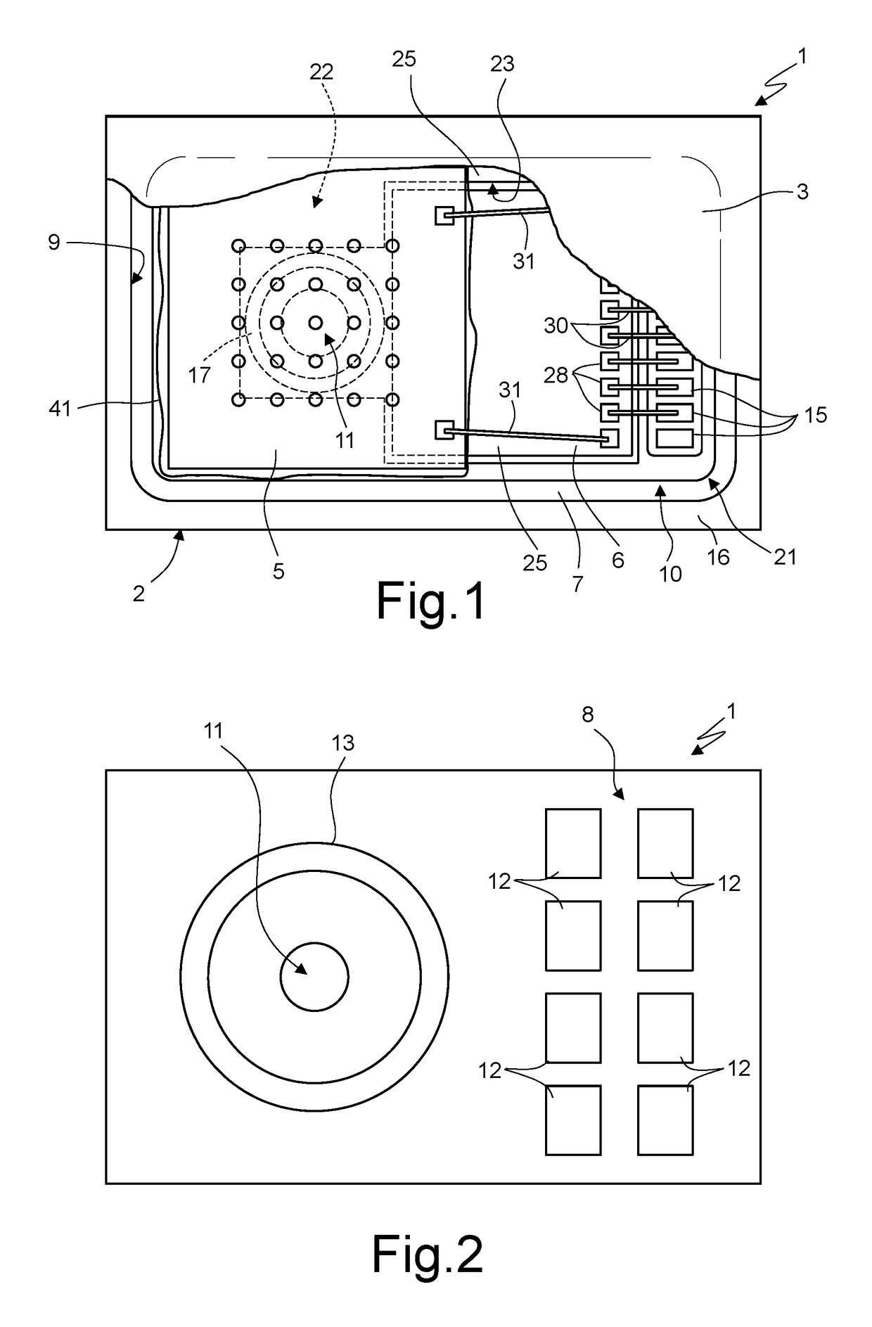
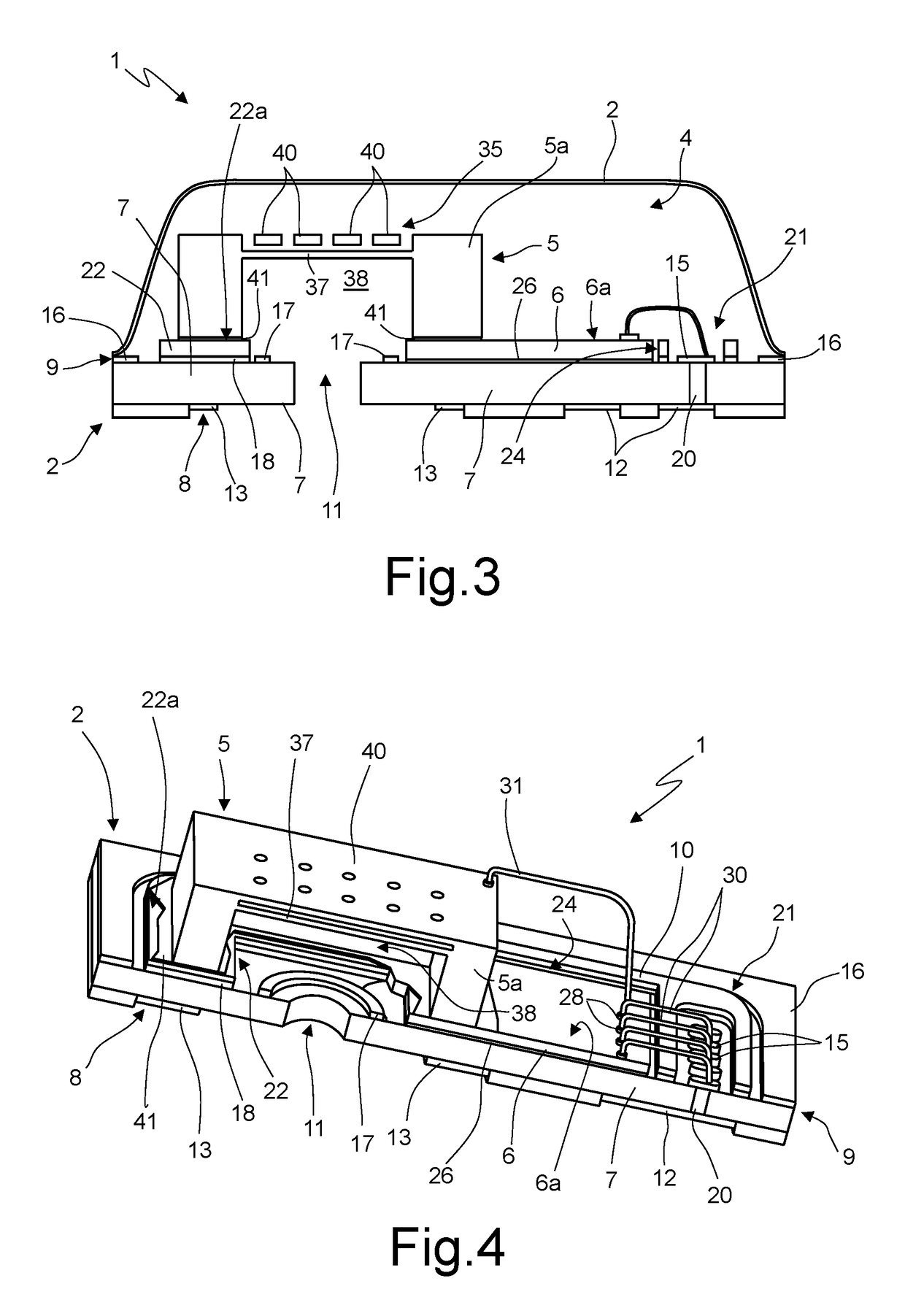
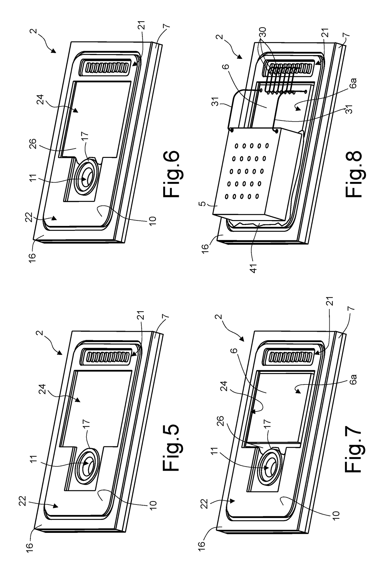
[0116]With reference to FIGS. 1 to 4, a microelectromechanical microphone according to one embodiment of the present disclosure is designated as a whole by the reference number 1 and comprises a substrate 2, a cap 3, a sensor chip 5, and a control chip 6. The sensor chip 5 and the control chip 6 are operatively coupled together.

[0117]The substrate 2 and the cap 3 are bonded together (FIG. 3) and form a package structure, inside which the sensor chip 5 and the control chip 6 are housed. The cap 3 has a protective function and also defines an acoustic chamber 4 of the microelectromechanical microphone 1.

[0118]In one embodiment, the substrate 2 may be a substrate of an LGA type and comprises: a core 7; an external metal layer 8 and an internal metal layer 9, for example of copper, on opposite faces of the core 7; and a sold...


PUM


Abstract

A microelectromechanical microphone includes: a substrate; a sensor chip, integrating a microelectromechanical electroacoustic transducer; and a control chip operatively coupled to the sensor chip. In one embodiment, the sensor chip and the control chip are bonded to the substrate, and the sensor chip overlies, or at least partially overlies, the control chip. In another embodiment, the sensor is bonded to the substrate and a barrier is located around at least a portion of the sensor chip.

Description

BACKGROUND[0001]Technical Field[0002]The present disclosure relates to microelectromechanical microphones and to processes for manufacturing microelectromechanical microphones.[0003]Description of the Related Art[0004]Microelectromechanical microphones are known, which comprise a first chip incorporating a microelectromechanical electroacoustic membrane transducer, and a second chip incorporating a control circuit or ASIC (Application-Specific Integrated Circuit). The electroacoustic transducer converts incident acoustic waves, which cause vibrations of a membrane, into electrical signals. For example, the membrane may be capacitively coupled to a reference electrode. The deformations of the membrane modify the capacitive coupling, which may be easily detected with a charge-amplifier circuit of the control circuit. The control circuit comprises signal-processing stages (for example, the charge-amplifier circuit) and components suitable for interacting with and enabling operation of ...

Claims


Application Information

Patent Timeline
Patent Type & Authority Patents(United States)
IPC IPC(8): H01L27/14H04R19/00H04R1/04B81B7/00H04R19/04H04R1/06H04R31/00
CPCH04R1/04B81B7/008B81B7/0061H04R19/005H04R19/04H04R31/006H04R31/00H04R2201/003B81B2201/0257H04R2499/11B81B2203/0127B81B2207/012B81B2207/07H04R1/06
Inventor BRIOSCHI, ROBERTOGRITTI, ALEXFORMOSA, KEVINBARBARA, PAUL ANTHONY
Owner STMICROELECTRONICS MALTA
Why Eureka
Try Eureka