Injection molding machine

a technology of injection molding machine and structure, which is applied in the field of injection molding machine structure, can solve the problems of increased vibration of the whole injection molding machine, increased weight of the machine base b>3/b>, and additional costs, so as to achieve the effect of reducing weight, improving vibration suppression effect, and improving overall vibration

Active Publication Date: 2016-03-17
FANUC LTD
View PDF3 Cites 0 Cited by
  • Summary
  • Abstract
  • Description
  • Claims
  • Application Information

AI Technical Summary

Benefits of technology

The present invention relates to an injection molding machine that can suppress vibration and reduce machine deformation or bending. This is achieved by configuring the machine base using a plurality of C-shaped members that are arranged and coupled together. This configuration, when compared to using a columnar strut or plate member, improves the vibration suppression effect. The struts can be placed on the side of the mold clamping mechanism to further enhance the vibration suppression effect. Additionally, at least one of the C-shaped members can have a through hole for weight reduction, which eliminates the need for a separate machine base lifting member. Overall, this invention offers an improved injection molding machine that reduces deformation, bending, and vibration in a simple structure.

Problems solved by technology

In such a case, the strut 6 may be deformed under the influence of an acceleration and deceleration operation of a mechanism unit such as the mold clamping apparatus 1 and the injection apparatus 2, leading to increased vibration of the whole injection molding machine.
To prevent such vibration, a method of making the strut thicker may be applied, but in such a case, the weight of the machine base 3 increases and an additional cost may be invited.
Even when a plate member is used for the machine base as disclosed by JP 2000-84979 A or JP 2014-61655 A described above, the plate member may be bent under the influence of an acceleration and deceleration operation of the mechanism unit, leading to increased vibration of the whole injection molding machine.
To prevent such vibration, a method of making the plate member thicker may be applied, but in such a case, an additional cost may be invited.

Method used


Image

  • Injection molding machine
  • Injection molding machine
  • Injection molding machine

Examples


first embodiment

[0022]First, an injection molding machine according to the present invention will be described with reference to FIGS. 1 to 3.

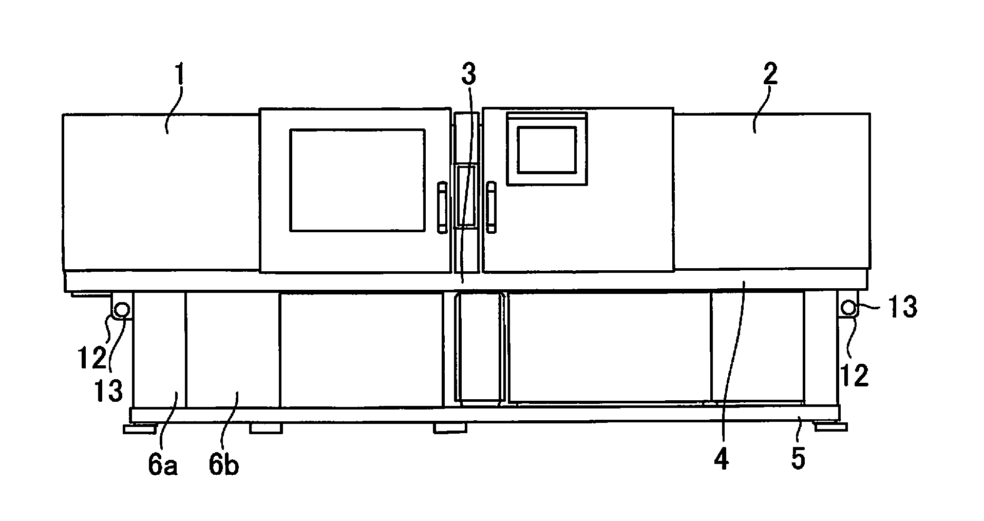
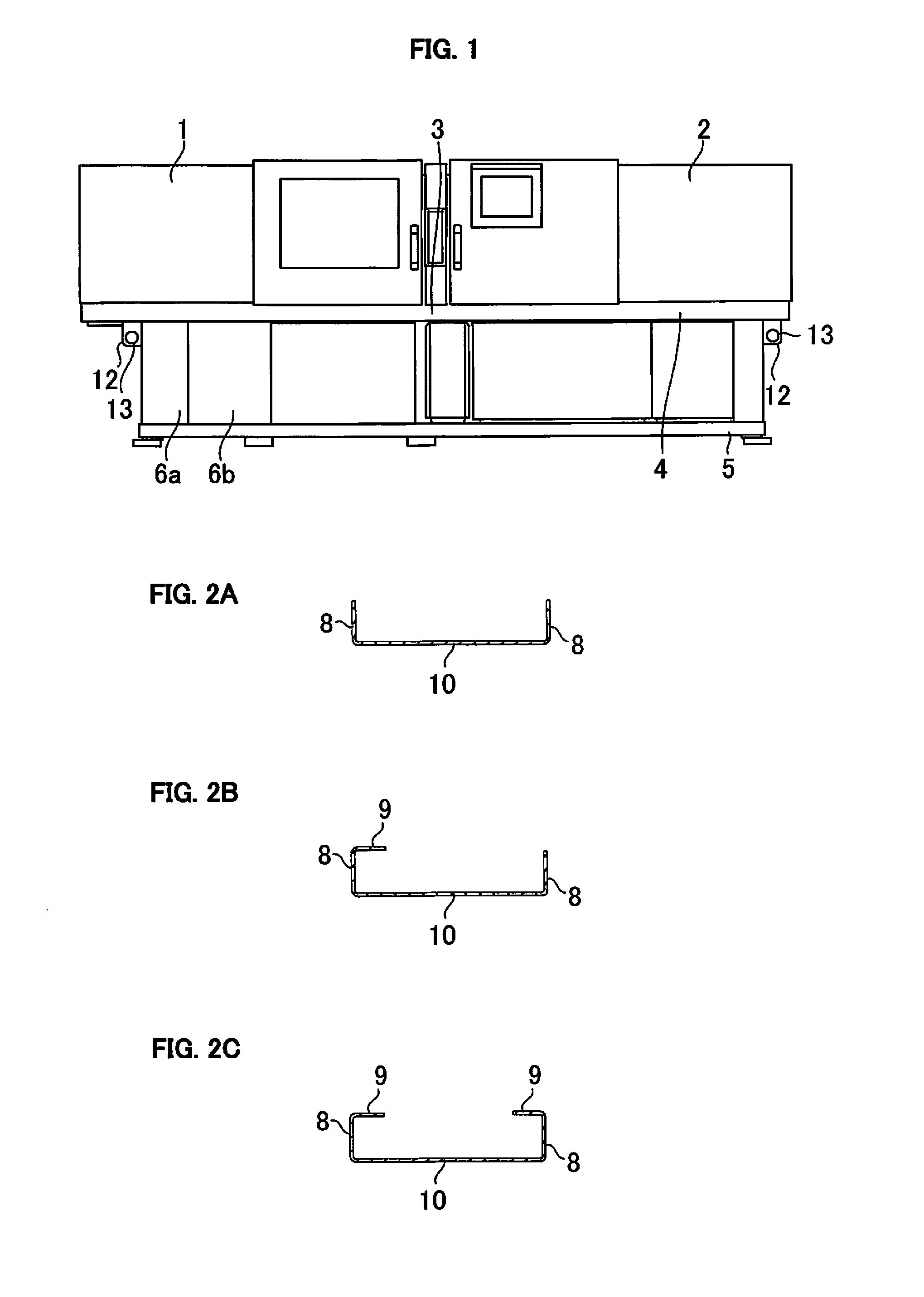
[0023]FIG. 1 is a diagram illustrating a structure of the first embodiment of an injection molding machine according to the present invention. The embodiment is characterized in that a strut 6 is configured by coupling a first strut element 6a and a second strut element 6b. Details of the shape of the strut 6 will be described later. Also in FIG. 1, a through hole is provided in a machine base 3 so that the machine base 3 can be lifted by inserting a rod-like machine base lifting member 12 into the through hole.

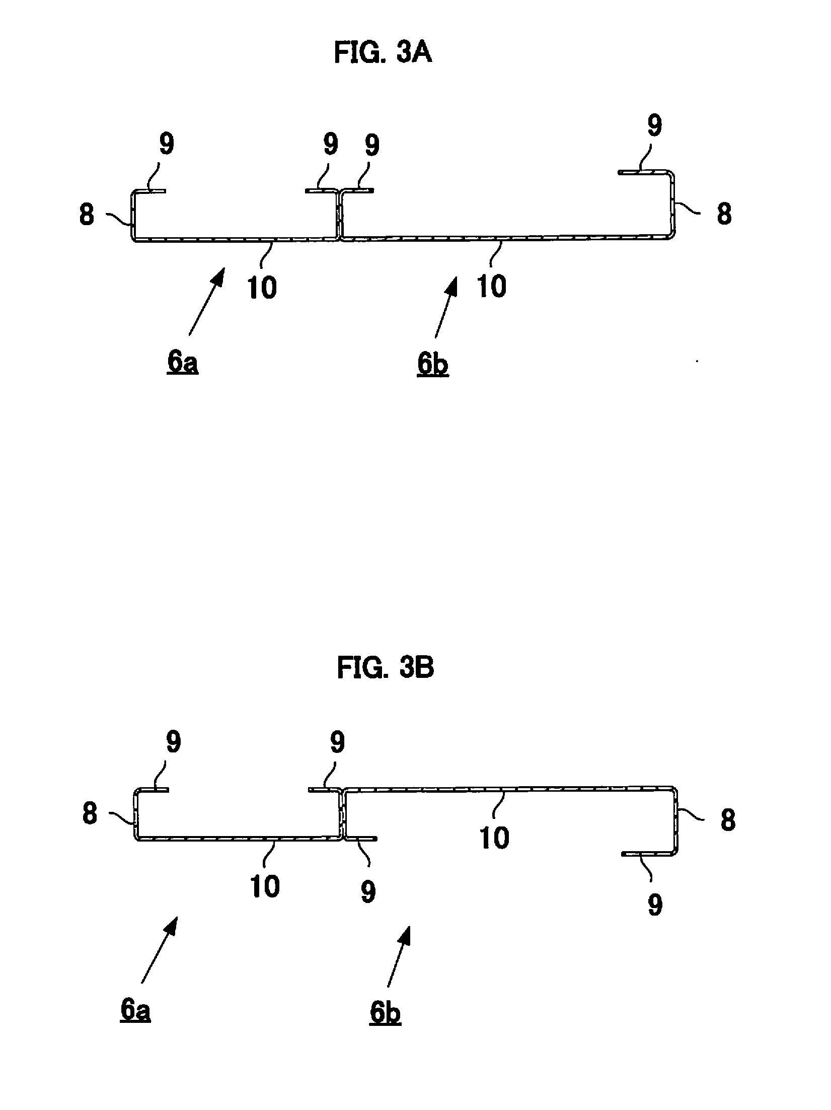
[0024]FIGS. 2A to 2C are diagrams illustrating examples in which strut elements are formed from metal plate members when the strut constituting the machine base of the injection molding machine in FIG. 1 is formed from the two strut elements, the first strut element 6a and the second strut element 6b.

[0025]In a first strut element formation example sh...

second embodiment

[0036]Next, the injection molding machine according to the present invention will be described with reference to FIG. 4.

[0037]The present embodiment is different from the first embodiment in that instead of the machine base lifting member 12 (FIG. 1) having a through hole, the machine base lifting member 12 is eliminated by forming a through hole 11 in one of the first strut element 6a and the second strut element 6b constituting the strut 6. Therefore, in the injection molding machine in the present embodiment, the machine base 3 can be lifted by inserting a rod-like machine base lifting member into the through hole 11 formed in a strut element constituting the strut 6. The other configuration of the injection molding machine in the present embodiment, for example, the overall configuration of the strut 6, the first strut element 6a, and the second strut element 6b is the same as in the first embodiment shown in FIGS. 2A to 3B.

[0038]In the example in FIG. 4, the through hole 11 is ...


PUM

PropertyMeasurementUnit
mold clamping forceaaaaaaaaaa
structureaaaaaaaaaa
closing speedaaaaaaaaaa

Abstract

A machine base of an injection molding machine on which a mold clamping mechanism and an injection mechanism are mounted includes a plurality of struts. At least one of these struts are constituted by arranging and coupling two members (strut elements) each formed by bending a metal plate and having a C cross section, thereby providing a structure to withstand vibrations of the mold clamping mechanism and the like mounted on the machine base.

Description

BACKGROUND OF THE INVENTION[0001]1. Field of the Invention[0002]The present invention relates to a structure of an injection molding machine in which a mold clamping mechanism and an injection mechanism are mounted on a machine base.[0003]2. Description of the Related Art[0004]An example of the structure of a conventional injection molding machine will be described using FIG. 5.[0005]The injection molding machine includes a mold clamping apparatus 1 that generates a mold clamping force by opening and closing a mold, an injection apparatus 2 arranged opposite to the mold clamping apparatus 1 to melt and inject a resin into the mold, and a machine base 3 on which the mold clamping apparatus 1 and the injection apparatus 2 are mounted.[0006]The machine base 3 includes a machine base top surface portion 4, a machine base undersurface portion 5, and a strut 6, and as shown in FIG. 5, the mold clamping apparatus 1 and the injection apparatus 2 are placed on the machine base top surface po...

Claims


Application Information

Patent Timeline
Patent Type & Authority Applications(United States)
IPC IPC(8): B29C45/64
CPCB29C45/64B29C45/17B29C45/1761
Inventor SUGAHARA, KEISUKENISHIMURA, KOICHI
Owner FANUC LTD
Why Eureka
Try Eureka