A resonance-free hydraulic vibration isolator and its vibration-damping module

A vibration isolator and non-resonant technology, which is applied in the direction of shock absorbers, shock absorber-spring combinations, shock absorbers, etc., can solve the troublesome installation of damper module spring pieces, loss of no resonance peak, strong impact resistance, and installation High requirements and other problems, to achieve the effect of facilitating installation and processing production, simple and convenient replacement process, and good resonance suppression effect

Active Publication Date: 2018-07-13
GUANGDONG POLYTECHNIC NORMAL UNIV +1
View PDF4 Cites 2 Cited by
  • Summary
  • Abstract
  • Description
  • Claims
  • Application Information

AI Technical Summary

Problems solved by technology

[0003] At present, military electronic equipment often adopts a modular shock-resistant peakless vibration isolator. The technology of this peakless vibration isolator has been disclosed in the patent document CN03131862.2. The vibration isolator is divided into a vibration damping spring module, a damper module, and a connection mechanism module. This modular shock-resistant peak-free vibration isolator suppresses resonance and can achieve a certain buffer performance, but this resonance suppression and buffering are mainly Relying on the spring sheet, in the actual use process, the spring sheet is prone to permanent deformation under the strong impact force of the vibration isolator, which leads to the failure of the damper module and becomes a small damping or no damping state. Only the vibration damping spring module It can play an effective supporting role, and loses the original function of no resonance peak and strong impact resistance, and the structure of this resonance-free peak vibration isolator is complicated, and the installation of the spring piece in the damper module is also troublesome, and the entire resonance-free peak isolation The installation or assembly process of the vibrator is cumbersome, which brings great inconvenience to the maintenance and replacement of vibration isolator parts
[0004] Patent No. ZL201520039978.9 in the prior art provides an improved non-resonant peak anti-strong impact vibration isolator for the above technologies. It mainly improves the damper, and is formed in the cavity of the mounting seat for The resonance suppression structure that suppresses the resonance of the vibration isolator can solve the problem of the failure of the damper module in the CN03131862.2 patent, but its overall structure is relatively complicated, which will inevitably lead to a relatively cumbersome processing technology and relatively high requirements for installation. It is not convenient to maintain and replace the spare parts. More importantly, the resonance suppression structure uses a single damping friction ring to cooperate with the damping pressure ring. The damping friction ring wears too much under strong impact force, which affects the damping effect and suppresses it. The rigidity of the damping support for lateral vibration is poor, and the performance of center return is not ideal, which affects the effect of lateral vibration isolation
[0005] In order to make up for a variable damping rear shock absorber with a built-in airbag (patent number 200420079303.9), the vacuum generated by insufficient oil replenishment in the rod cavity, the excessive wear of the piston leads to the increase of the radial clearance, and the difficulty in controlling the compression damping. Defects, the patent CN201110245924.4 proposes a two-way hydraulic limit shock absorber, which can provide an effective recovery limit in the vertical direction, but its structure is not ideal for the vibration suppression in the horizontal direction, which limits this two-way hydraulic Application field and effect of limit shock absorber

Method used


Image

  • A resonance-free hydraulic vibration isolator and its vibration-damping module
  • A resonance-free hydraulic vibration isolator and its vibration-damping module
  • A resonance-free hydraulic vibration isolator and its vibration-damping module

Examples


Embodiment Construction

[0026]The following will clearly and completely describe the technical solutions in the embodiments of the present invention with reference to the accompanying drawings in the embodiments of the present invention. Obviously, the described embodiments are only some, not all, embodiments of the present invention. Based on the embodiments of the present invention, all other embodiments obtained by persons of ordinary skill in the art without creative efforts fall within the protection scope of the present invention.

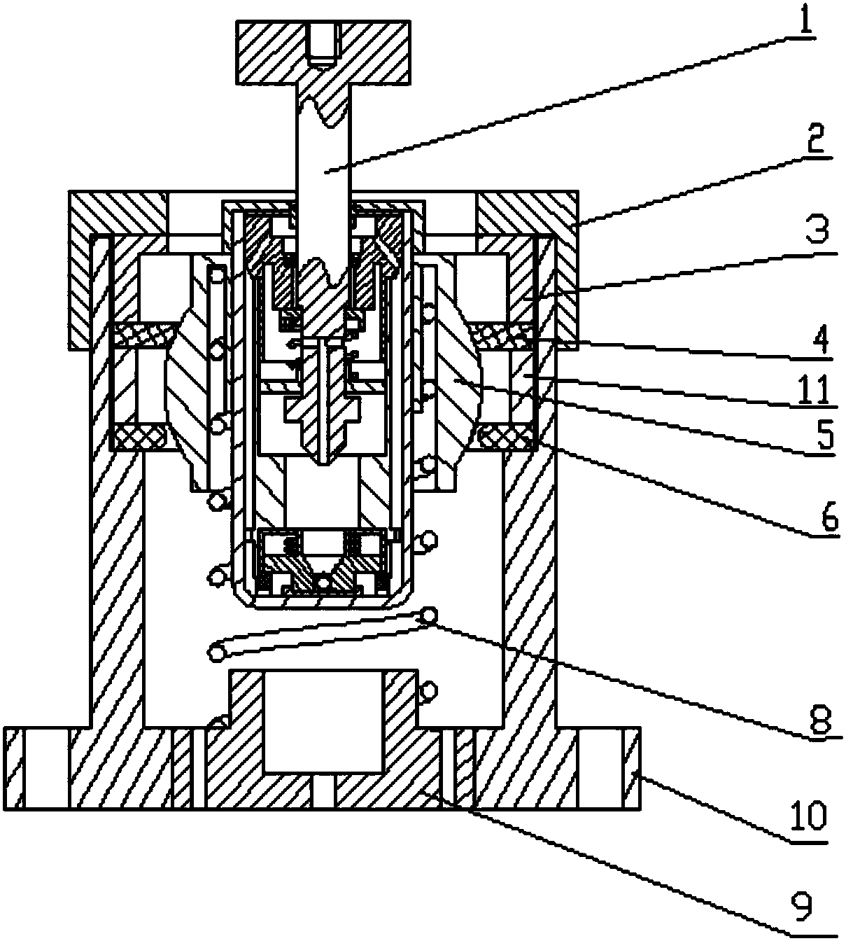
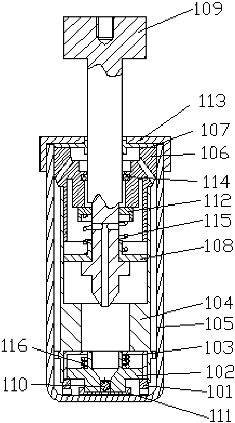
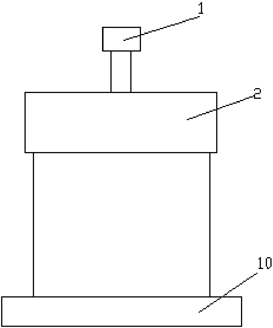
[0027] Figure 1 to Figure 3 It shows the schematic diagram of the structure and appearance of the hydraulic vibration isolator without resonance peak in the embodiment of the present invention. The damping module in the embodiment of the present invention includes: a hydraulic limit shock absorber (1), a main spring (8), The hydraulic limit shock absorber (1) is embedded in the non-resonant peak hydraulic vibration isolator, and the hydraulic limit shock absorber (...


PUM


Abstract

The invention provides a resonance-peak-free hydraulic vibration isolator and a vibration reducing module of the resonance-peak-free hydraulic vibration isolator. The resonance-peak-free hydraulic vibration isolator comprises the vibration reducing module, a damping module and a connecting module. The vibration reducing module comprises a hydraulic limiting vibration reducing device and a main spring. The damping module comprises a waist-drum-shaped damping sleeve, a first damper and a second damper. The connecting module comprises an upper end cover, an upper limiting end cover, a middle cylinder, a lower end cover with a cylindrical protrusion, and a base. According to the resonance-peak-free hydraulic vibration isolator, the implementation structure of the damping module is simple, the structure of the combination between the bi-directional hydraulic vibration reducing device and the double dampers in the damping module can be matched with the waist-drum-shaped damping sleeve to provide stable damping force in the perpendicular direction and the horizontal direction, perpendicular bi-direction limiting can be achieved, a good centering reset effect on transverse vibration is achieved, and the resonance damping effect is good.

Description

technical field [0001] The invention relates to the technical field of vibration isolators, in particular to a hydraulic vibration isolator without a resonance peak and a vibration damping module thereof. Background technique [0002] The non-resonant peak vibration isolator can effectively suppress resonance, realize no amplification in the resonance area, and can effectively prevent electronic equipment from being damaged in the resonance area in time, causing the performance of electronic equipment to decline or even fail. The vibration isolator with stable and reliable anti-strong impact can Effectively avoid damage to electronic equipment caused by impact environments, especially high-precision military electronic equipment in the face of complex and diverse impact environments. Once they are subjected to strong impacts, they are easily damaged and invalidated, greatly weakening or even losing the combat effectiveness of weapons, equipment or tools For example, the stro...

Claims


Application Information

Patent Timeline
Patent Type & Authority Patents(China)
IPC IPC(8): F16F13/06F16F9/32F16F9/34
CPCF16F9/3214F16F9/3221F16F9/3235F16F9/34F16F13/06
Inventor 杨勇杨舜琦杨军沈伟谦
Owner GUANGDONG POLYTECHNIC NORMAL UNIV
Why Eureka
Try Eureka