
Method for obtaining an arm for multi-link suspensions of automotive vehicles and a suspension arm

a technology for automotive vehicles and suspension arms, applied in the field of multi-link suspensions, can solve the problems of high cost, tensile, compressive and torsional stresses on the suspension arm,

Inactive Publication Date: 2016-03-17
ENG DEV FOR AUTOMOTIVE IND SL
View PDF16 Cites 19 Cited by
  • Summary
  • Abstract
  • Description
  • Claims
  • Application Information

AI Technical Summary

Benefits of technology

The present invention relates to a method for making an arm for multi-link suspensions of automotive vehicles. The method reduces the weight, costs, and number of processes required for manufacturing the arm, while supporting elastic or ball and socket articulations at the ends of the arm in an optimal manner. This allows the arm to control the drop, convergence, or forward movement of the wheels. Additionally, the method reduces production costs by about 10% due to the reduced number of processes involved in manufacturing the arm.

Problems solved by technology

Given its open section, this suspension arm is vulnerable to tensile, compressive and torsional stresses, as well as in its fatigue behavior.
However, this suspension arm requires a specific final geometry or shape given that in addition to acting as a joint between the stub axle and subframe, it also has the function of acting as a link with other tertiary elements such as the case of the damper, which causes it to have this complex final shape, involving a large number of processes for manufacture, and therefore having a high cost.

Method used


Image

  • Method for obtaining an arm for multi-link suspensions of automotive vehicles and a suspension arm
  • Method for obtaining an arm for multi-link suspensions of automotive vehicles and a suspension arm
  • Method for obtaining an arm for multi-link suspensions of automotive vehicles and a suspension arm

Examples


Embodiment Construction

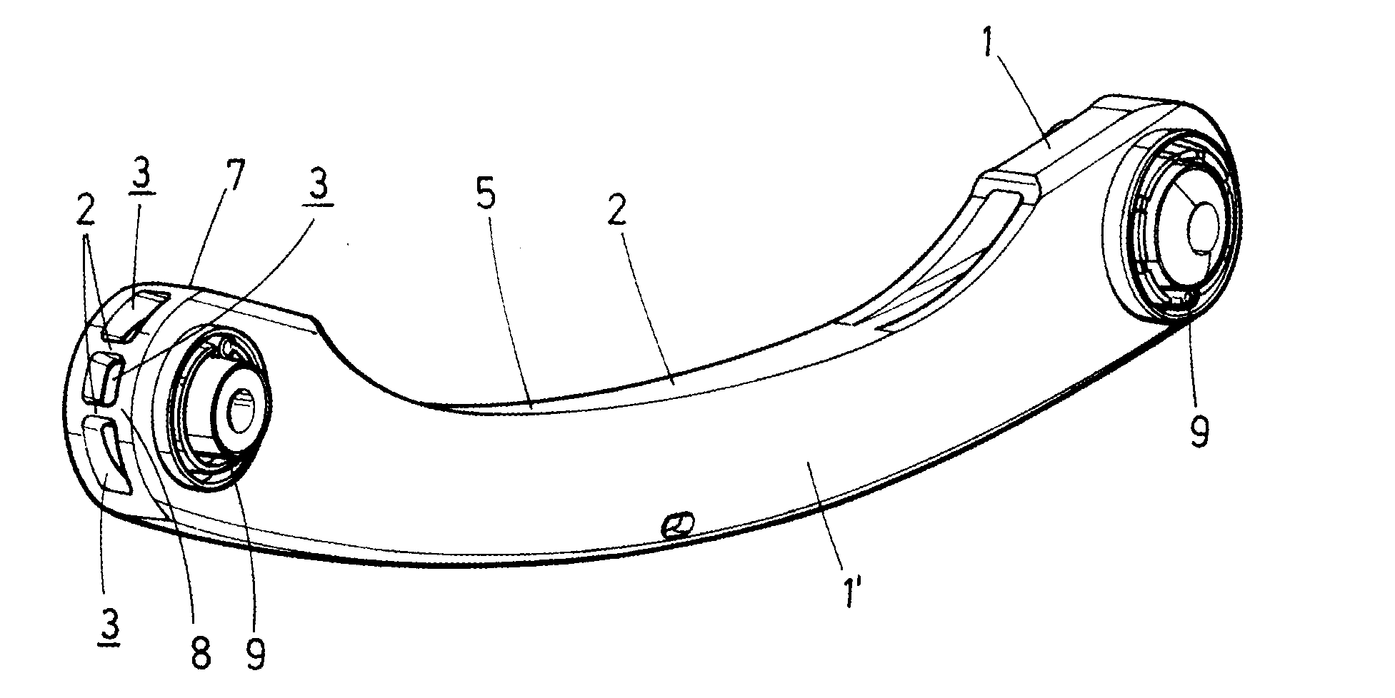
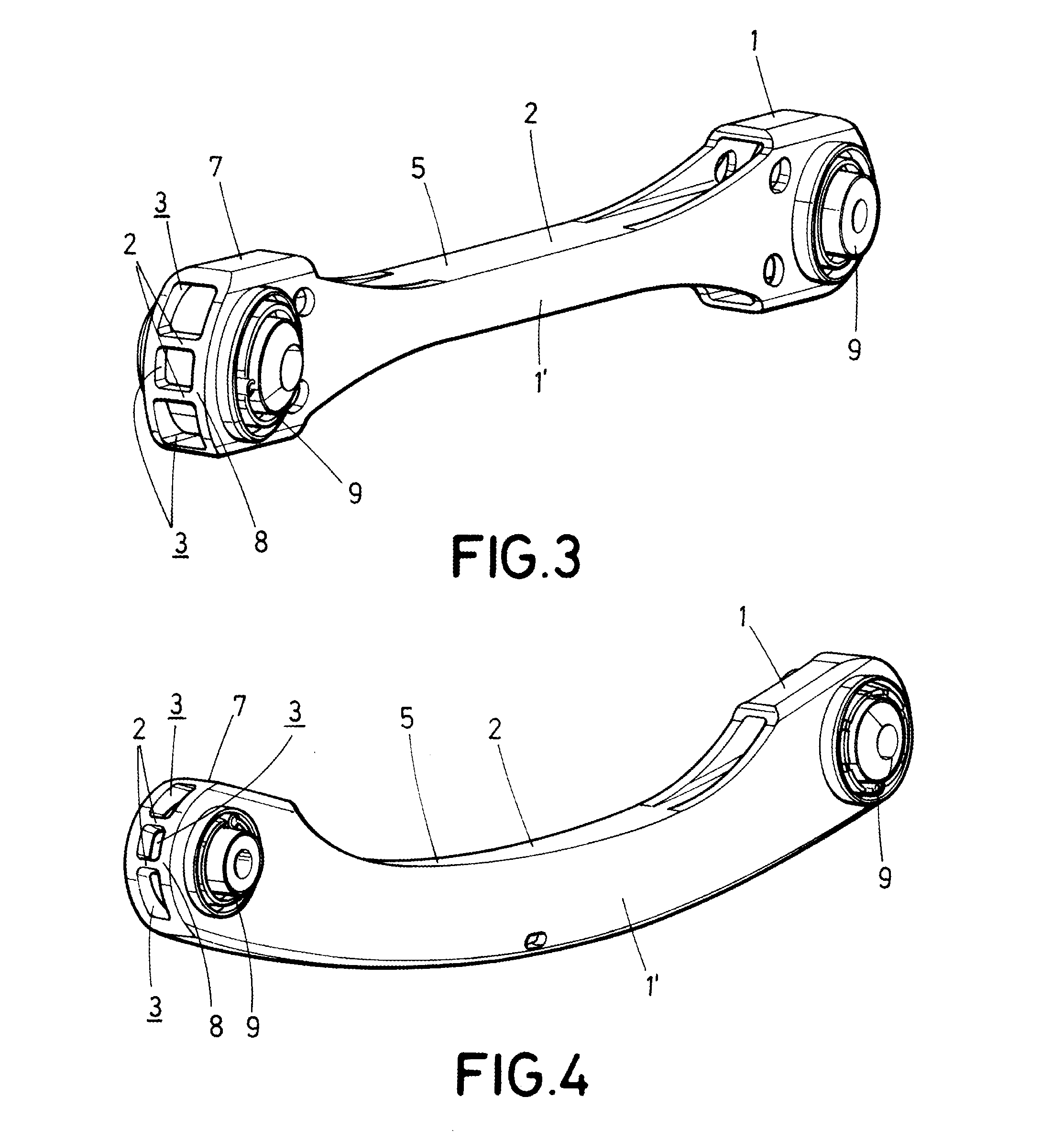
[0007]A first aspect of the present invention relates to a method for obtaining an arm for multi-link suspensions of automotive vehicles, which allows reducing the weight of the arm, the costs and the number of processes required for manufacturing the body of the arm, which is responsible for physically joining the connecting elements, either ball and socket or elastic articulations, housed at the ends of the arm.

[0008]The method proposed by the invention comprises the following sequential steps:

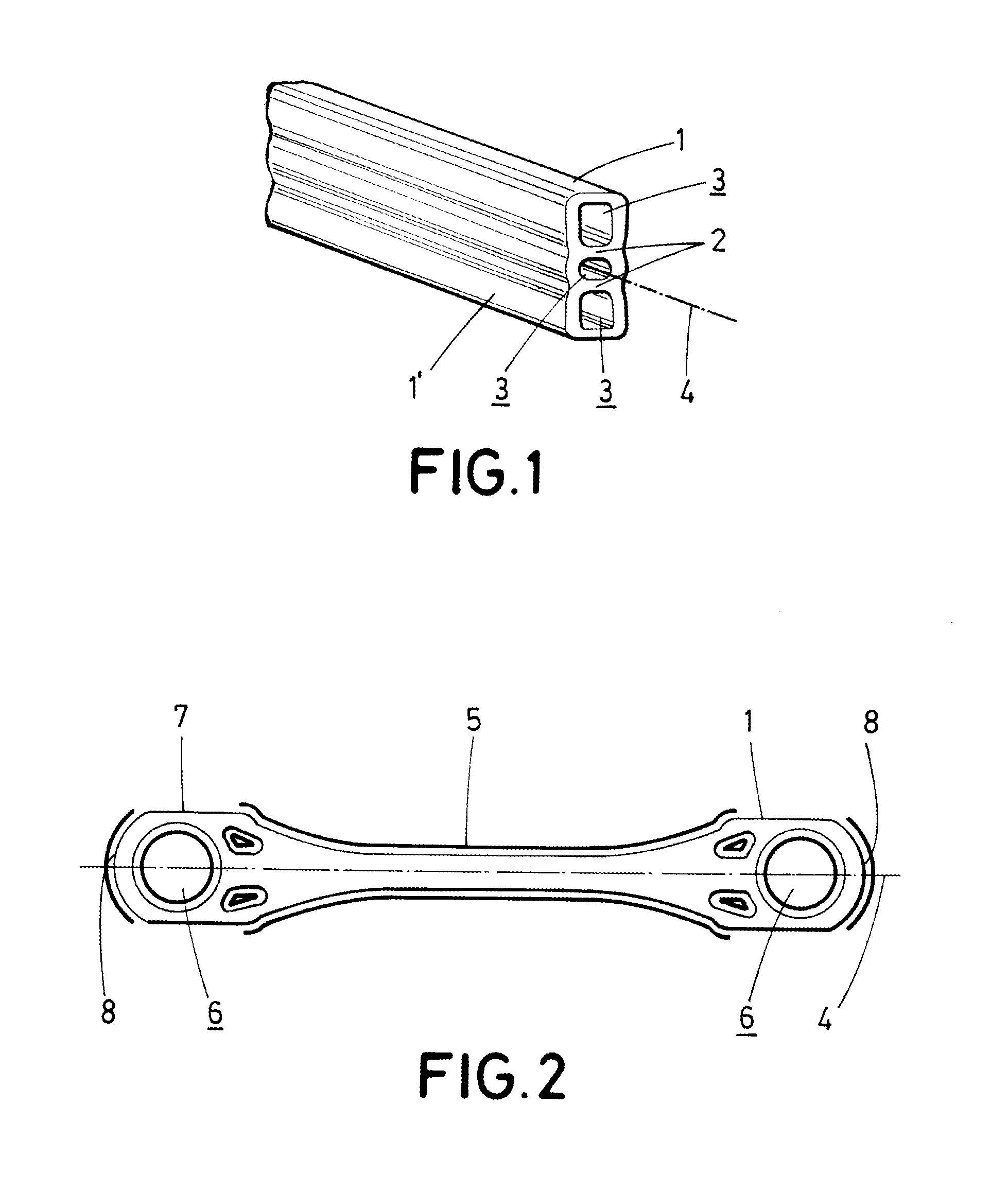
[0009]a) extruding a hollow profile the cross-section of which has a closed outer contour formed by side walls and comprising at least one inner partition internally splitting the profile into at least two inner cavities,

[0010]b) transversely cutting the extruded profile into sections corresponding with the length of the arm to be obtained, according to a longitudinal axis of the arm,

[0011]c) in a central section of the arm, machining at least one side wall having no inner partition extendin...


PUM

PropertyMeasurementUnit
lengthaaaaaaaaaa
areaaaaaaaaaaa
rigidityaaaaaaaaaa

Abstract

The present invention relates to a method for obtaining an arm for multi-link suspensions of automotive vehicles and a suspension arm, where the method comprises:e) extruding a hollow profile the cross-section of which has a closed outer contour formed by side walls (1, 1′) and comprising at least one inner partition (2) internally splitting the profile into at least two inner cavities (3),f) transversely cutting the extruded profile into sections corresponding with the length of the arm to be obtained, according to a longitudinal axis (4) of the arm,g) in a central section (5) of the arm, machining at least one side wall (1) having no inner partition (2) extending therefrom without the machining ever reaching said at least one inner partition (2), andh) in the side walls (1′) having said at least one inner partition (2) extending therefrom, making an end opening (6) in each end area (7) of the arm, between which the central section (5) is arranged.

Description

TECHNICAL FIELD OF THE INVENTION[0001]The present invention has application in the field of the automotive component industry, specifically in multi-link suspensions.BACKGROUND OF THE INVENTION[0002]In a multi-link suspension, wheels are joined to a central subframe of a vehicle by means of a plurality of arms linking or joining the wheel stub axle with said subframe. Such suspensions are the object of recent technological developments made in the automotive industry. The main reason for using this suspension lies in the great rigidity it provides to the vehicle laterally, successfully preventing the well-known oversteer phenomenon. It also provides greater directional stability in the direction of travel and allows absorbing a high percentage of vibrations and noise. Multi-link suspensions therefore provide the vehicle with greater maneuverability, safety and superior comfort while travelling.[0003]Within such suspensions, the suspension arm is a kinematic element the function of w...

Claims


Application Information

Patent Timeline
Patent Type & Authority Applications(United States)
IPC IPC(8): B60G7/00B23P15/00
CPCB60G7/001B23P15/00B60G2206/82B60G2206/8105B60G2206/811B23P2700/14B23P13/04B60G2206/11B60G2206/8103B60G2206/8111B60G3/04
Inventor MOSTEIRO, GOYOAGA, JOSE, RAMON
Owner ENG DEV FOR AUTOMOTIVE IND SL
Learn More