Aerial refueling navigable device, system and method

a technology of navigable devices and aircraft, applied in the field of aviation, can solve the problems of increasing the difficulty of larger and less maneuverable planes, if even possible, and insufficient and/or practical solutions for aerial refueling of commercial aircraft, and achieves the effects of reducing drag effects, facilitating attaching, and reducing the cross-sectional area of the hose of the fuel-transmitting medium

Inactive Publication Date: 2016-03-17
ELSAWAH ZIAD AHMED MOHAMED ALI HUSSEIN
View PDF13 Cites 13 Cited by
  • Summary
  • Abstract
  • Description
  • Claims
  • Application Information

AI Technical Summary

Benefits of technology

[0011]Described herein is a device, system, and method of aerial refueling for overcoming one or more of the aforementioned disadvantages, which allows precise positioning for connecting a fuel-transmitting medium with an inlet fuel inlet / refueling port located in certain areas of commercial fuel-receiving planes (such as the along the wings). In some instances / embodiments, such a refueling connection may be accomplished without requiring certain adaptations (that are often otherwise required by prior art devices, systems, and methods) to the fuel-receiving plane. The novel method may comprise a fuel-transmitting medium being trailed by a fuel-giving plane, which has at the end of the fuel-transmitting medium a navigable flying unit capable of precise mid-air navigation and fastening to the surface of the fuel-receiving plane and of establishing a connection between the fuel-transmitting medium and the fuel inlet / refueling port located on the plane's surface. In one embodiment and if necessary, the navigable unit is additionally maneuverable along a surface of the fuel-receiving plane.
[0017]The navigable unit may also comprise, in one embodiment, a means for softening the impact of the navigable unit against the plane surface, such as for example a cushion-like feature. For example, in one embodiment, the incoming air along the leading edge of the navigable unit may be channeled to an inflatable canvas designed to have first contact with the plane surface, which inflatable canvas may provide sufficient cushioning to avoid damaging either the plane surface or the navigable unit upon impact. After the initial cushioned impact, the canvas may deflate and thereby facilitate attaching to the plane surface in the manner described above, and also any additional movement of the navigable unit along the plane's surface (as described above). In a related embodiment, the inflation of the inflatable canvas may utilize internal means, such as an air compressor.
[0018]Embodiments of the fuel-transmitting medium may vary, but may be flexible in many degrees of freedom, which flexibility might be accomplished in some embodiments using corrugated sections. Furthermore, to transfer a higher volume of fuel more quickly, the cross-sectional area of the hose of the fuel-transmitting medium may be greater than conventional hoses. To make such wider designs more practical and also to reduce drag effects (and also applicable to fuel-transmitting medium embodiments that do not comprise hoses having greater cross-sectional areas), the fuel-transmitting medium may comprise aerodynamic surfaces, which in one embodiment may comprise symmetrical airfoil. The shape of said aerodynamic surfaces are configured to reduce the drag coefficient according to the position and intended configurations of the fuel-transmitting medium while traveling in mid-air and being dragged behind the fuel-giving plane and fastened to the navigable unit. For example, rather than having a shape and a drag coefficient similar to that of a sphere or a cylinder (when the fuel-transmitting medium has some vertical and / or lateral components to its shape with respect to passing air—rather than running directly backward from the fuel-giving plane to the fuel-receiving plane, with respect to the passing air), the shape and drag coefficient may resemble more that of a streamlined body, and may have in one embodiment a plurality of sections of such streamlined bodies / aerodynamic surfaces.

Problems solved by technology

Prior art devices methods essentially do not provide sufficient and / or practical solutions for aerial refueling of commercial aircraft, in part due to the necessity of certain structural formalities, and also because of the substantial difficulty of precisely positioning a fuel-transmitting medium to establish a connection between the fuel-giving plane and the fuel-receiving plane while both are in mid-air and traveling at high speeds.
If the fuel-receiving plane is not manufactured incorporating such structures, the plane must then have certain adaptations performed, which if even possible can be prohibitively expensive for most commercial applications.
A commercial fuel-receiving plane's fuel ports / inlets, for example, may be located in areas where it may not be advisable to attach a probe, or difficult if not impossible for a flying boom to reach.
Specifically, many commercial aircraft have fuel inlets / refueling ports located on or under wings or in certain spots along the fuselage that are difficult to connect with a fuel-transmitting medium for several reasons using either the probe and drogue system or the flying boom system.
The task is even more challenging for larger and less maneuverable planes, such as commercial (as opposed to fighter) jets, or when probes are located in other not-so convenient areas of the plane.
Attaching probes along the wings, for example, would present several other obvious challenges, such as requiring in some instances that a pilot look to the side at the wing for a significant period of time while the plane is traveling forward at high speeds and in close proximity to the fuel-giving plane.
In addition, some commercial planes simply do not provide good structural accommodation for retrofitting probes on wings or other harder-to-reach areas of the fuselage.
In the case of the flying boom system, although the boom may be said to be “maneuverable,” its range of motion is too limited to allow the boom to reach many parts of the fuel-receiving plane where fuel inlets might be located, such as often the wings.
Even if theoretically possible in some instances, the limited orientation of the boom further makes connecting with fuel inlets located on certain areas of the fuel-receiving plane extremely problematic if not impossible.
Adding to the difficulty, since the boom operator is generally stationed in the rear-center of fuel-giving plane, in some instances more difficult the vantage point of the boom operator may also make maneuvering the boom to certain areas of the fuel-receiving plane (such as the wing) more challenging.
Moreover, if the boom were to miss a wing target, the potential impact of the boom against the wing creates added danger.

Method used


Image

  • Aerial refueling navigable device, system and method
  • Aerial refueling navigable device, system and method
  • Aerial refueling navigable device, system and method

Examples


Embodiment Construction

[0031]“Fueling port,”“fuel port,” and “refueling port” may all be used interchangeably and are defined herein as an area comprising a fuel inlet for receiving the connecting means of the navigable unit. “Controllable” is also defined to include “manipulable.”

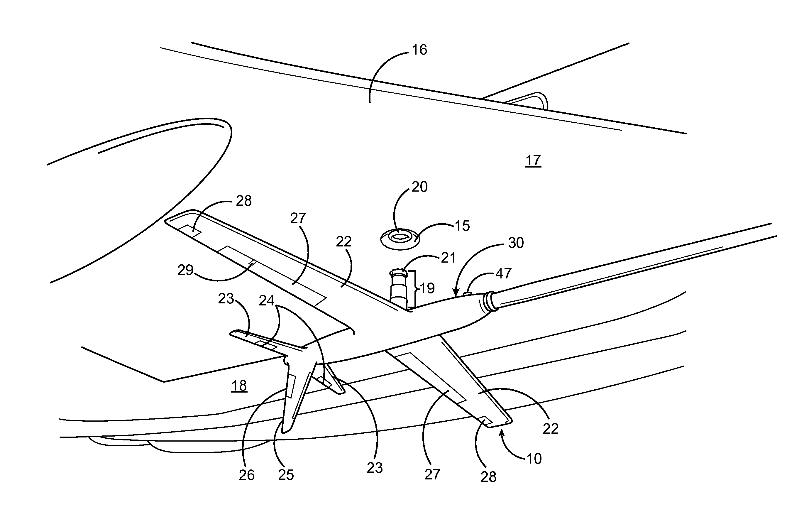
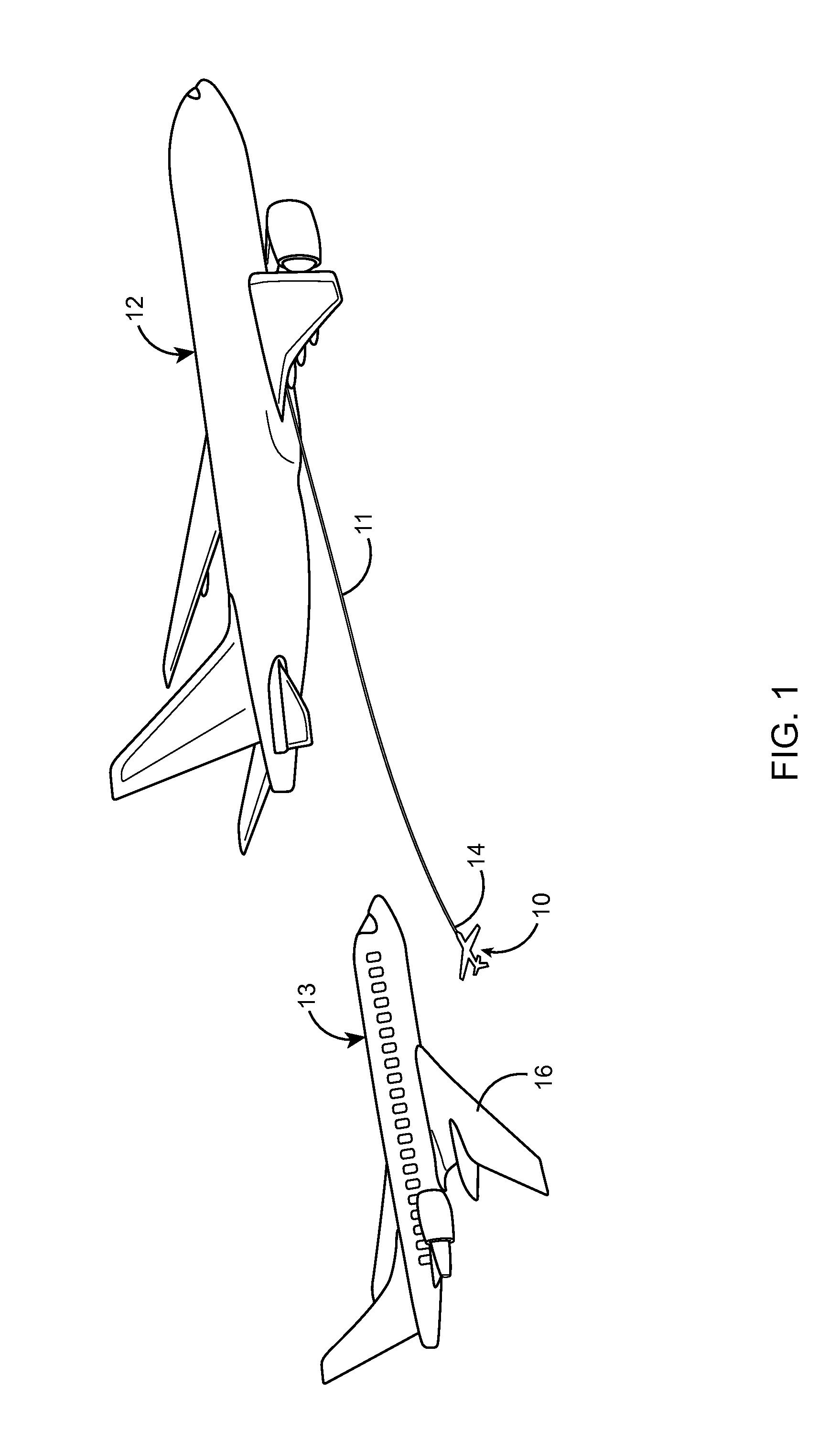
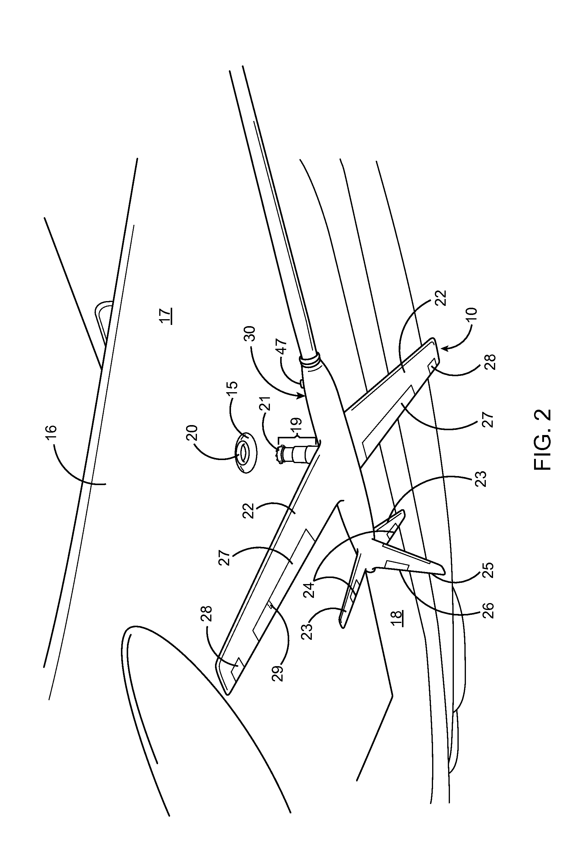
[0032]Turning to the drawings, FIG. 1 illustrates a navigable flying probe unit 10 carrying a fuel transmitting medium 11 from a fuel-giving plane 12 to a fuel-receiving plane 13, and also a method of aerial refueling comprising trailing said fuel-transmitting medium 11 from the fuel-giving plane 12, and maneuvering it 11 through the air towards the wing 16 of the fuel-receiving plane 13 using, on one end 14 of the fuel-transmitting medium 11, the navigable unit 10, and (as also shown in FIG. 2) by utilizing the navigable unit's 10 controllable aerodynamic surfaces 18 to precisely position the navigable unit 10 to the refueling port 15 located on the surface 17 of the wing 16 of the fuel-receiving plane 13. Then, as shown in FIG...


PUM


Abstract

A device, system, and method for facilitating aerial refueling. The device is a navigable flying unit for more precise positioning to establish a fuel-transmitting connection with a fuel inlet of a fuel-receiving plane (including a fuel inlet located on the wing of a commercial aircraft). The device comprises controllable aerodynamic surfaces for mid-air maneuvering while attached to a fuel-transmitting medium being trailed by a fuel-giving plane. The navigable unit may also comprise a means for, if necessary, moving along a surface of the fuel-receiving plane for more precise positioning, and a means for attaching to the surface of the fuel-receiving plane and / or a fuel port thereof, as well as a means for coupling with the fuel inlet in order to establish a fuel-transmitting connection. The in-air maneuvering of the device and fuel-transmitting medium may be facilitated in one embodiment, by the fuel-transmitting medium comprising aerodynamic surfaces configured for reducing drag.

Description

FIELD OF INVENTION[0001]The present invention is in the technical field of aviation and more particularly relates to aerial refueling devices, methods, and systems.BACKGROUND OF INVENTION AND DESCRIPTION OF PRIOR ART[0002]Prior art aerial refueling methods and devices have not provided adequate solutions for aerial refueling of commercial aircraft. Aerial refueling involves the connecting of a fuel-transmitting medium between a fuel-giving plane and a fuel-receiving plane while both are in mid-air flight. Although this feat has been accomplished in a number of ways over the years, prior art devices and methods have not done so safely without requiring either a high level of skill from the pilot of the fuel-receiving plane or significant structural adaptations or peculiarities to the fuel-receiving plane. The early “crossover” aerial refueling system, for example, involved a fuel-receiving plane dropping a line and a fuel-giving plane also trailing a line with a large hook on the end...

Claims


Application Information

Patent Timeline
Patent Type & Authority Applications(United States)
IPC IPC(8): B64D39/04B64D39/06
CPCB64D39/06B64D39/04
Inventor ELSAWAH, ZIAD, AHMED, MOHAMED, ALI, HUSSEIN
Owner ELSAWAH ZIAD AHMED MOHAMED ALI HUSSEIN
Why Eureka
Try Eureka