
Arrangement and method for outputting light signals at a medical-technical installation

a technology of medical technology and light signals, applied in the field of arrangement and a method of outputting light signals at a medical technology installation, can solve the problems of anxiety and fear, many patients feel uncertain about their health, and the patient experiences feelings of uncertainty, so as to reduce the care effort of the personnel, increase the perception and conscious processing, and reduce the time expenditure for examination

Inactive Publication Date: 2016-03-24
SIEMENS AG
View PDF2 Cites 10 Cited by
  • Summary
  • Abstract
  • Description
  • Claims
  • Application Information

AI Technical Summary

Benefits of technology

This patent describes an arrangement and method that use biofeedback to help control a patient's physiological parameters during a medical examination. This non-medicinal method aims to make the patient aware of their own body's response to the examination, which can help them relax and make the examination less stressful. This approach can also reduce the need for medication and increase the patient's well-being. Overall, this technology helps improve the patient's experience and the medical staff's efficiency during the examination.

Problems solved by technology

Many of the patients feel uncertain with regard to their health.
These circumstances have the effect that the patient experiences feelings of uncertainty, anxiety and fear, which are also brought about by the confined situation in the gantry.
The radiological examination is therefore felt to be unpleasant or even threatening.
However, the anxiety and fear may adversely influence the quality of the examination.
By way of example, the patient's nervousness may have the effect that, in thoracic examinations, the patient may not hold his / her breath for a sufficiently long period of time.
Moreover, the patient's pulse may be too high for cardiological examinations owing to his / her agitation.

Method used


Image

  • Arrangement and method for outputting light signals at a medical-technical installation
  • Arrangement and method for outputting light signals at a medical-technical installation

Examples


Embodiment Construction

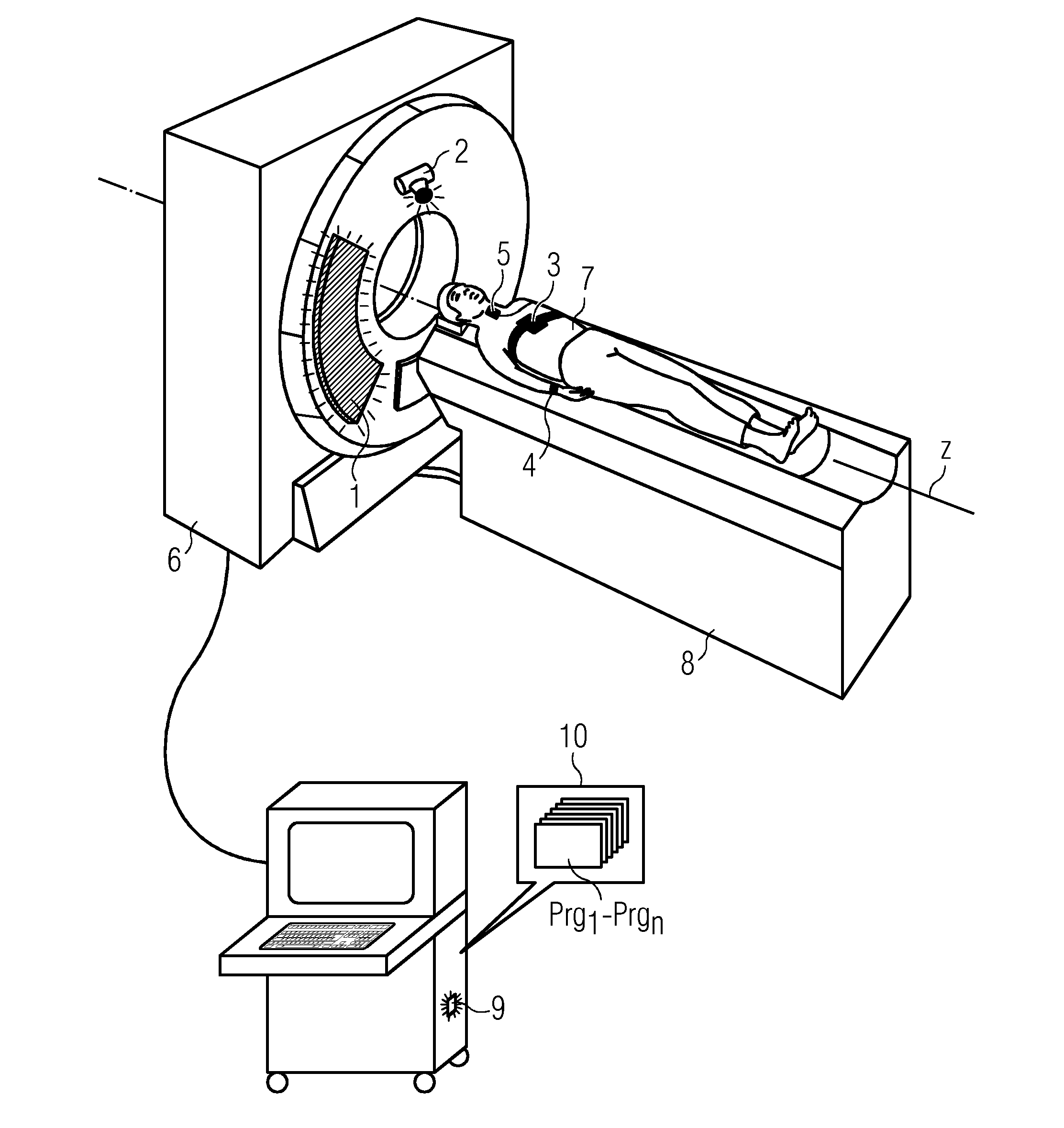
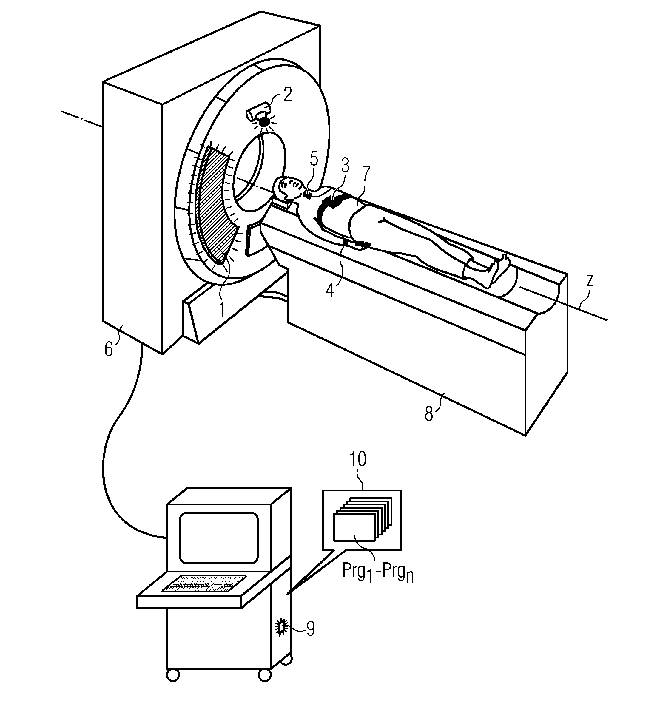
[0027]FIG. 1 shows one embodiment of a medical-technical installation 6 (e.g., a computed tomography apparatus including a tubular gantry). A patient 7 lies on a patient table 8 and is introduced into the gantry in the z-direction for examination. Two lighting units 1, 2 are mounted on the medical-technical installation 6 such that the light emitted by the two lighting units 1, 2 appears in the field of view of the patient 7. For this purpose, any desired lighting units 1, 2 may be used. The lighting units 1, 2, may be configured, if appropriate, with regard to electrotechnical boundary conditions on the medical-technical installation 6. In principle, the lighting units 1, 2 used may be, for example, LED lamps or planar LED panels since these enable the light color to be controlled. The respective lighting unit 1, 2 may also be equipped with a projection lens and irradiate the medical-technical installation 6 from a remote position such that light is reflected by the medical-technic...


PUM


Abstract

The principle of biofeedback is used to incorporate a patient into a control loop for relaxation by light signals. For this purpose, a sensor measures physiological parameters of the patient. By virtue of the fact that the respective physiological parameter controls a lighting parameter such as light color or light intensity of a lighting unit using the signal processing of a microprocessor in a control loop, the patient acquires visual biofeedback with respect to his / her physiological parameter. Endogenous regulation processes of the patient are thus made accessible to his / her consciousness. The outputting of the light signals is continued until the patient is prepared for the required examination and there is no need for a further administration of medicaments for calming. The work results of the medical-technical installation may be kept optimal as a result of the relaxation of the patient even without administration of medicaments.

Description

[0001]This application claims the benefit of DE 10 2014 218 826.1, filed on Sep. 18, 2014, which is hereby incorporated by reference in its entirety.BACKGROUND[0002]The present embodiments relate to an arrangement and a method for outputting light signals at a medical-technical installation.[0003]A computed tomography apparatus substantially includes a round gantry, in which a patient to be examined is positioned by the patient being moved on a patient table into the gantry. The examination area, the computed tomography apparatus, and the entire surroundings are unfamiliar to many patients. Many of the patients feel uncertain with regard to their health. These circumstances have the effect that the patient experiences feelings of uncertainty, anxiety and fear, which are also brought about by the confined situation in the gantry. The radiological examination is therefore felt to be unpleasant or even threatening. However, the anxiety and fear may adversely influence the quality of th...

Claims


Application Information

Patent Timeline
Patent Type & Authority Applications(United States)
IPC IPC(8): A61B5/00A61B5/01A61B5/021A61B5/024A61B5/0476A61B5/0488A61B5/053A61B5/08A61B5/145A61B6/00A61B6/03A61M21/02H05B37/02
CPCA61B5/486A61M21/02A61B6/035A61B6/44A61B19/52A61B5/7271A61B5/7264A61B5/08A61B5/024A61B5/021A61B5/14542A61B5/01A61B5/0531A61B5/0488A61B5/0476H05B37/0227A61B6/4441A61M2021/0044A61M2205/502A61M2205/52A61M2230/06A61M2230/10A61M2230/14A61M2230/205A61M2230/30A61M2230/42A61M2230/50A61M2230/60A61M2230/65H05B45/20H05B47/105A61B90/36
Inventor BRAUN, CHRISTOPHRACKOW, BASTIAN
Owner SIEMENS AG
Learn More