Control device for injection molding machine and screen display method

a control device and technology of an injection molding machine, applied in the direction of manufacturing tools,foundry moulding equipment, instruments, etc., can solve the problems of user forgetting which hierarchy, user fatigue, and impaired operation, so as to reduce the load on the user

Active Publication Date: 2016-03-24
U MHI PLATECH CO LTD
View PDF7 Cites 13 Cited by
  • Summary
  • Abstract
  • Description
  • Claims
  • Application Information

AI Technical Summary

Benefits of technology

[0032]According to the present invention, when a user wants to redisplay a display image (previously displayed image) which is not displayed at the present time, it is possible to display the previously displayed image by simply giving a scroll instruction. Therefore, according to the present invention, since a case where a user must remember the name of the previously displayed image while depending on a user's memory or a case where a user selects the previously displayed image from the menu screen again is not required, it is possible to reduce a load on the user.

Problems solved by technology

However, the selection of the menu screen is hierarchically logical, the selection of the menu button needs to be repeated a number of times corresponding to the hierarchy in order to reach the desired image, and operability is impaired.
Particularly, the hierarchical configuration may cause the user to forget which hierarchy at which the desired image has been displayed.
Accordingly, stress on a user increases, the operation of the injection molding machine is delayed, and productivity decreases.

Method used


Image

  • Control device for injection molding machine and screen display method
  • Control device for injection molding machine and screen display method
  • Control device for injection molding machine and screen display method

Examples


Embodiment Construction

[0046]Hereinafter, the present invention will be described in detail based on an embodiment shown in the accompanying drawings.

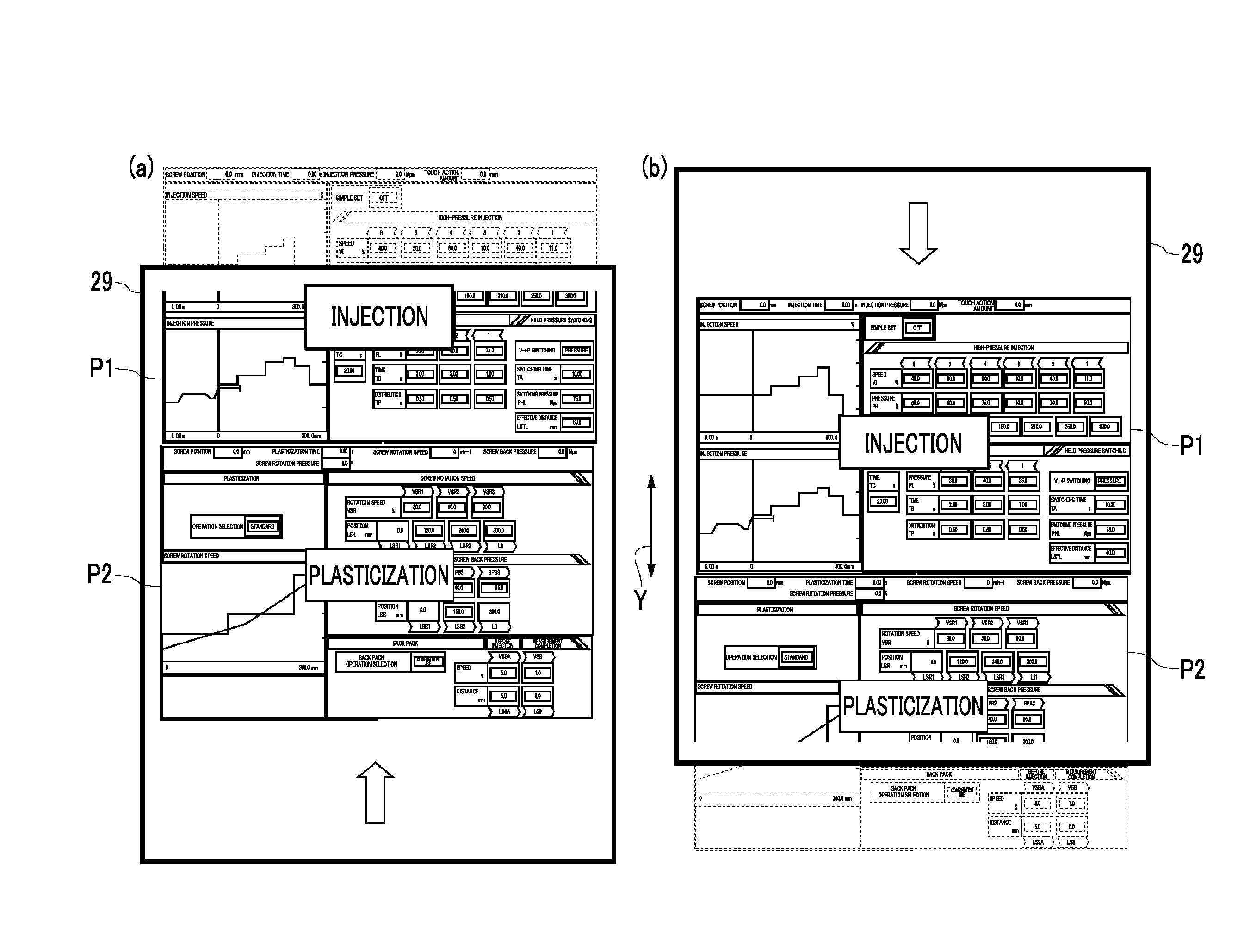
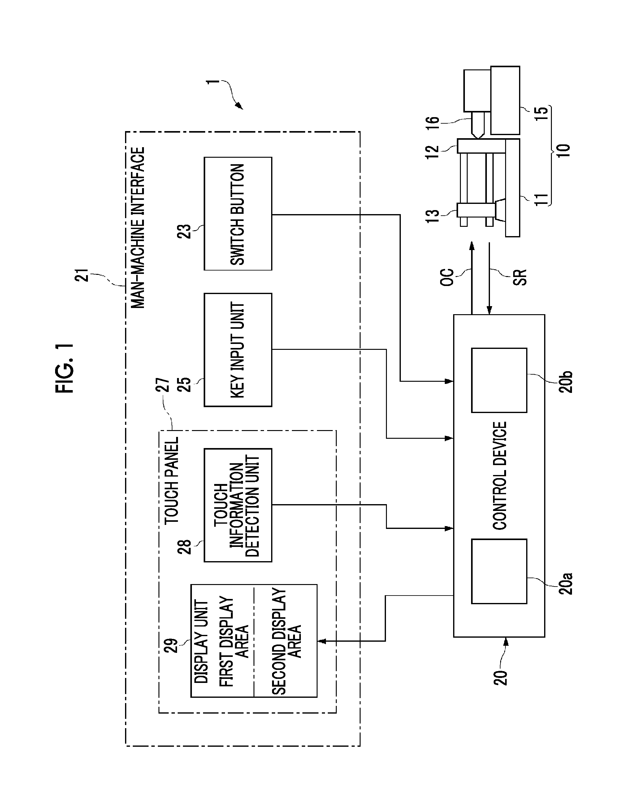
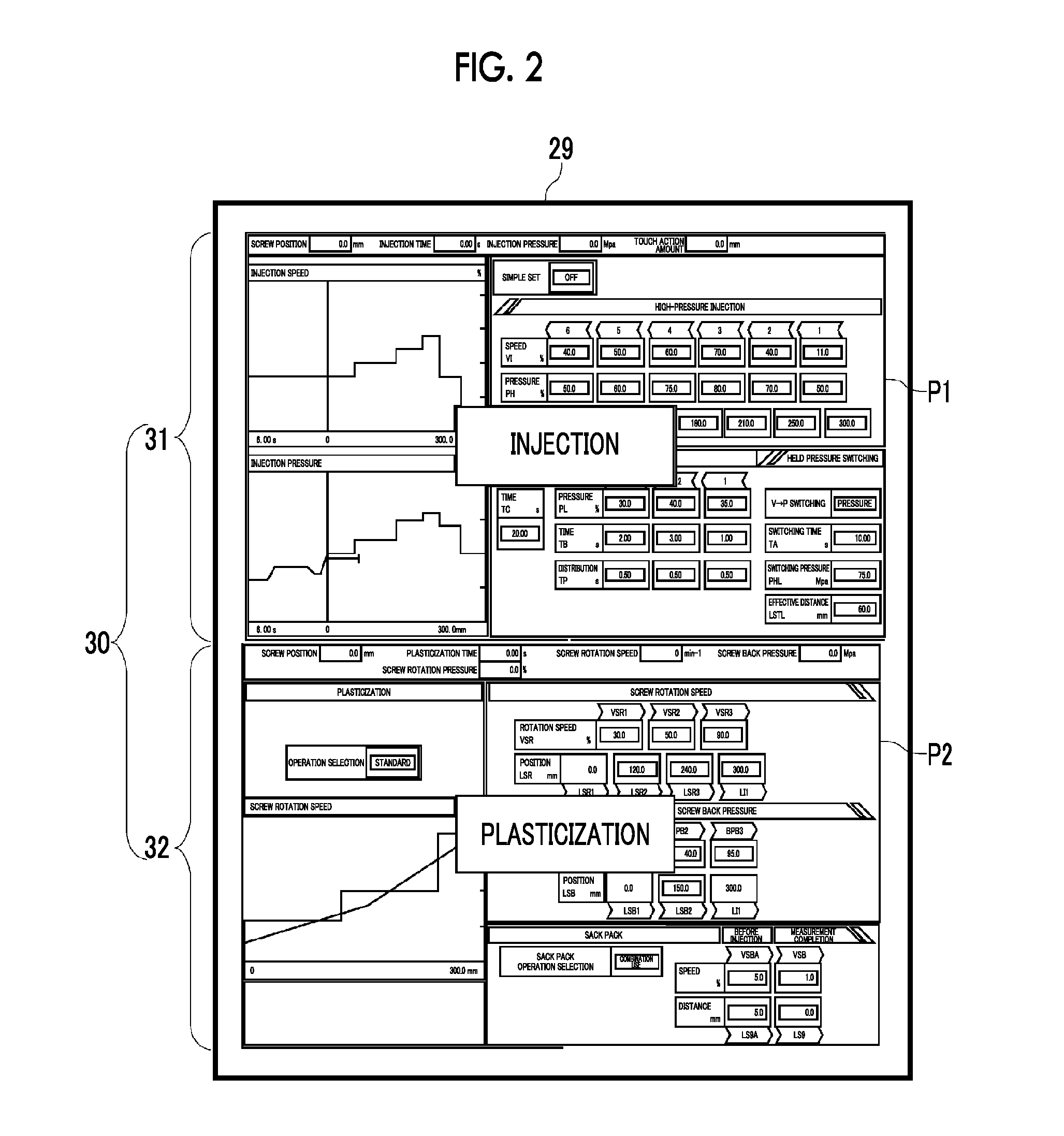
[0047]An injection molding machine 1 of the present embodiment includes a molding machine main body 10, and a control device 20 which controls operations of the molding machine main body 10. An injection molding machine 1 has characteristics with respect to a method for performing display on a display unit 29 included in the control device 20. In addition, the present embodiment is described with reference to the injection molding machine 1 which is driven by a hydraulic actuator (hydraulic mechanism). However, instead of a hydraulic actuator, an electric actuator which is driven by an electric motor such as a servo motor, an inverter motor, or an interior permanent magnet motor may be applied to the injection molding machine 1.

[0048]The molding machine main body 10 includes a mold clamping unit 11 and a plasticizing unit 15.

[0049]The mold clamping unit 11 i...


PUM

PropertyMeasurementUnit
areaaaaaaaaaaa
stressaaaaaaaaaa
timeaaaaaaaaaa

Abstract

Provided is a control device for an injection molding machine, capable of reducing the load on a user when re-displaying a previously displayed screen. The control device (20) for the injection molding machine (1) controls the display of display images on a display unit (29). This control device (20) divides the display unit (29) into a first display area (31) and a second display area (32) and, if an instruction to scroll in the vertical direction is received when a first display image (P1) is displayed in the first display area (31) and a second display image (P2) is displayed in the second display area (32), synchronously scrolls the first display image (P1) and the second display image (P2) whilst maintaining the relative positions of the first display image (P1) and the second display image (P2).

Description

TECHNICAL FIELD[0001]The present invention relates to a control device for an injection molding machine, and particularly, to display of a screen included in a control device.BACKGROUND ART[0002]An injection molding machine includes a plurality of devices such as a mold clamping device, an injection device, or a molded part discharging device, as components, and when the injection molding machine is operated, operation conditions should be set by a control device with respect to each of the plurality of devices. In general, in the injection molding machine, a setting screen or an execution value display screen is provided on the control device in each of the plurality of devices or in each of the related devices. Accordingly, in the setting screen of the control device, switching and input between many control screens should be diversely performed.[0003]In general, a display button is provided on each screen, in which a list is displayed on a menu screen, corresponding to each setti...

Claims


Application Information

Patent Timeline
Patent Type & Authority Applications(United States)
IPC IPC(8): B22D17/32B29C45/76
CPCB22D17/32B29C2045/7606B29C45/762B29C45/76B29C2945/76939B29C2945/76949B29C45/766G06F3/0482G06F3/04842
Inventor OKOCHI, YASUOTAKII, TAKASHIKARIYA, TOSHIHIKO
Owner U MHI PLATECH CO LTD
Why Eureka
Try Eureka