
Display systems and methods employing time multiplexing of projection screens and projectors

Active Publication Date: 2016-03-24
BARCO NV
View PDF3 Cites 7 Cited by
  • Summary
  • Abstract
  • Description
  • Claims
  • Application Information

AI Technical Summary

Benefits of technology

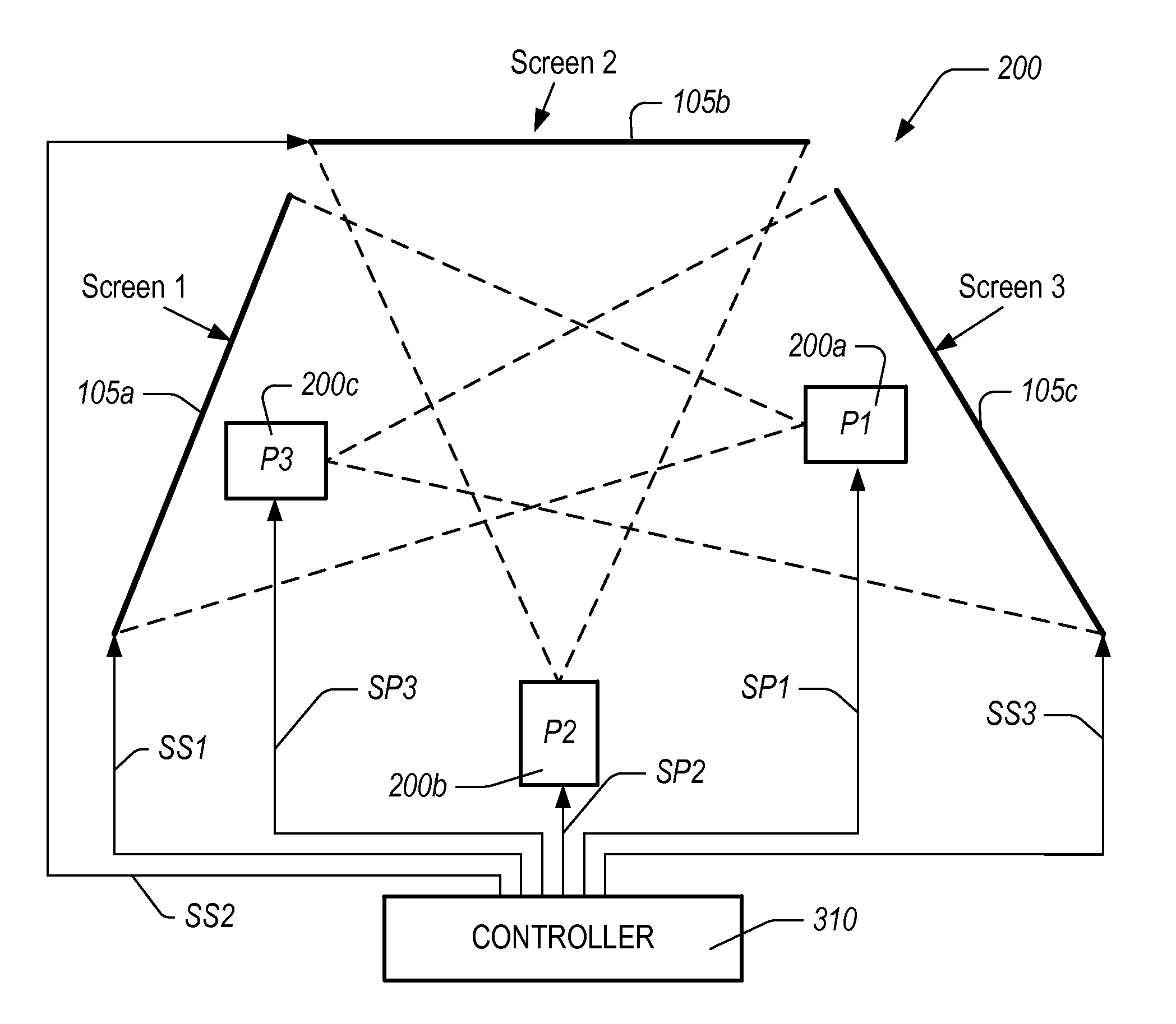
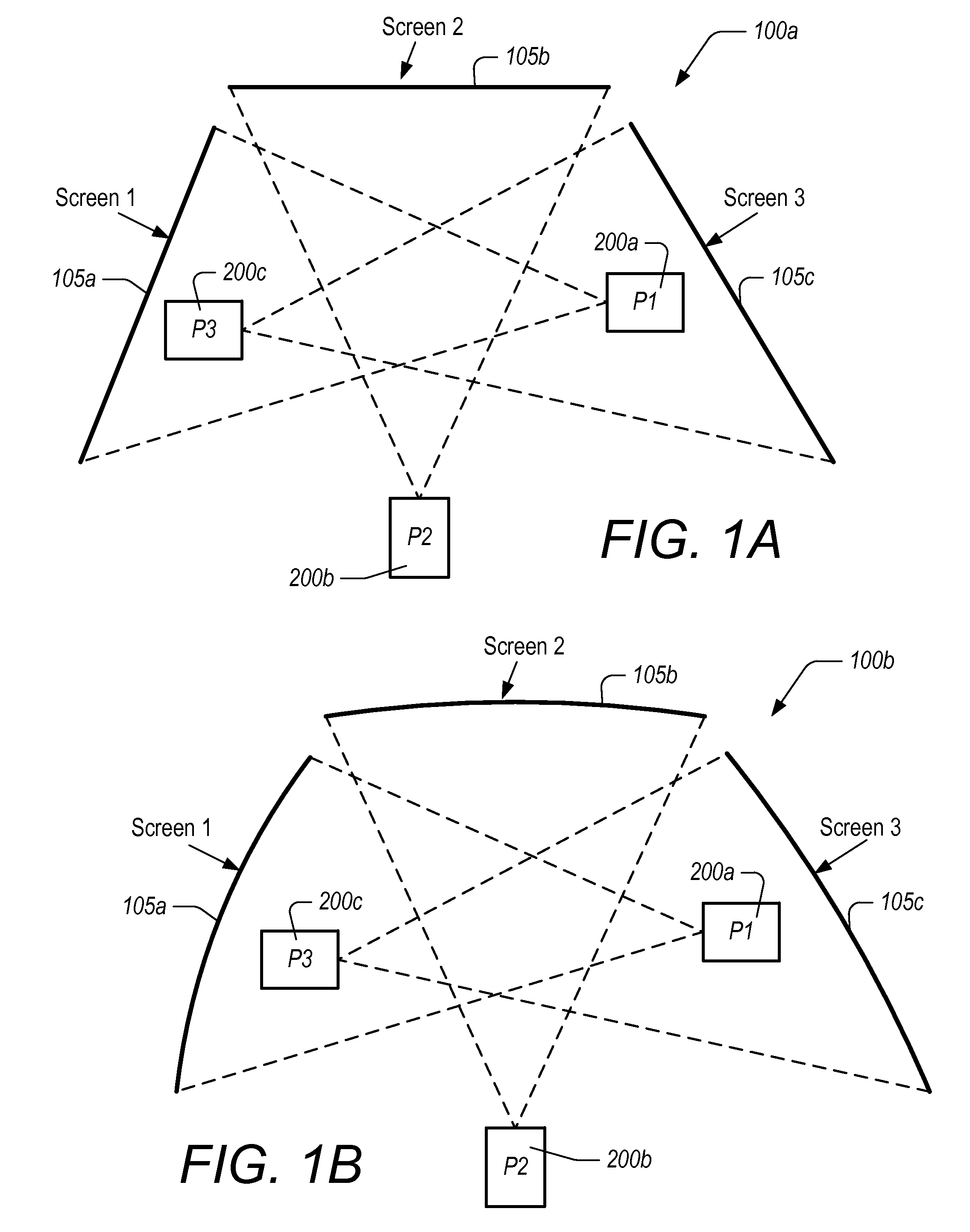
This patent is about a system and method for creating an immersive display with multiple projection surfaces that can be viewed from different angles. However, the challenge of cross-talk or cross-reflection can reduce the quality of the images provided in the system. To address this, the patent proposes a solution that includes a plurality of curved or plane screens that switch between a diffuse reflective state, a scattering state and a dark state. The screens are synchronized with one or more projectors, so that the images or frames of video are projected when the associated screen is in the diffuse reflective state. This system can be controlled by a central controller to synchronize the screens and projectors. The technical effect of this patent is to create an immersive display system with multiple projection surfaces that minimize cross-talk and provide high-contrast, high-dynamic range images for viewers.

Problems solved by technology

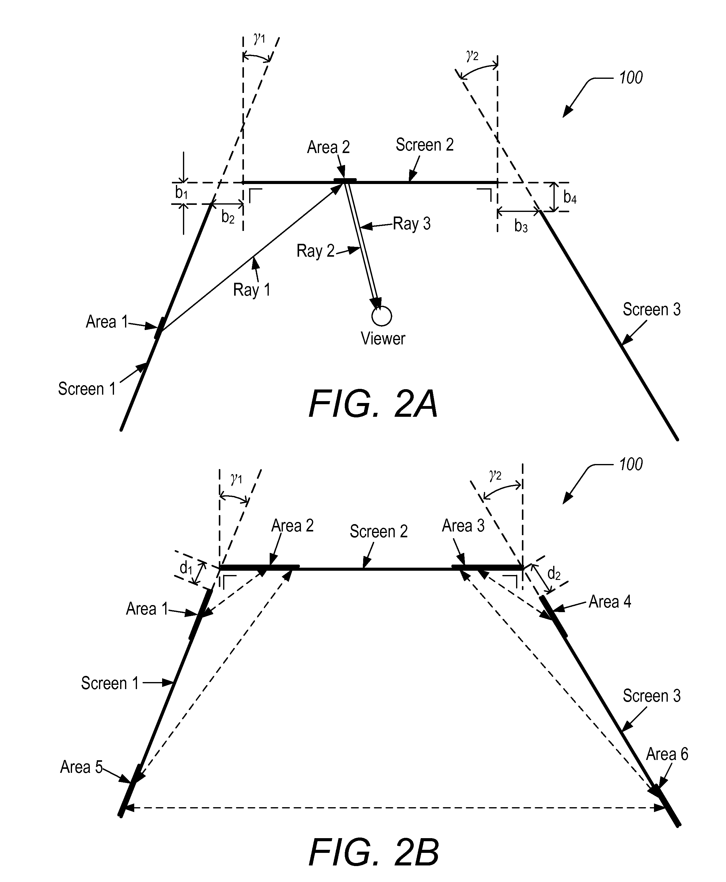
However, having multiple projection surfaces can result in light being reflected from a first projection surface to a second projection surface and then to the viewer.
Such mixing of light on the plurality of projection surfaces can reduce the contrast ratio and / or dynamic range of the projection surfaces, thereby diminishing the quality of the images provided in the immersive display system.
This mixing of light can be referred to as cross-talk or cross-reflection and can be a challenge in immersive display systems.
This challenge may be even more difficult to overcome for immersive display systems designed for a relatively large group of people, such as in a movie theater, due at least in part to the wide range of viewing angles of the viewers in the audience.

Method used


Image

  • Display systems and methods employing time multiplexing of projection screens and projectors
  • Display systems and methods employing time multiplexing of projection screens and projectors
  • Display systems and methods employing time multiplexing of projection screens and projectors

Examples


example screens

with Multi-Layer Structure

[0084]FIG. 7A illustrates an example screen 700 having a multi-layer structure, wherein the screen 700 is a front projection screen in the scattering state. The screen includes multiple layers including an anti-reflection element or glare-suppression element 701, transparent substrates 702, 704 with a transparent conductive layer on the inner side, a PDLC layer 703 in the diffuse reflective state (e.g., because no electric field is applied to the PDLC layer 703), a light absorbing element 705, an optional support substrate 706, and an optional adhesive layer 707. Ray 1 represents incident light which is strongly scattered by the PDLC layer 703 due at least in part to no electric field being applied and the nematic droplets of the PDLC layer 703 strongly scattering the incident light.

[0085]The PDLC layer 703 includes an electrically controllable PDLC film. The PDLC film can have a thickness of, for example and without limitation, 10 μm and can be sandwiched ...


PUM

PropertyMeasurementUnit
Timeaaaaaaaaaa
Lengthaaaaaaaaaa
Frequencyaaaaaaaaaa

Abstract

An immersive display system is disclosed that includes screens configured to mitigate reduction in contrast ratio due at least in part to peripheral light incident on the screens. The immersive display system includes at least two screens and at least two projector systems. The screens have a multi-layered structure configured to selectively reflect light for controlled periods of time. Adjacent screens can be configured to selectively reflect light during different periods of time. The projector systems can be configured to project video onto their respective screens while the associated screen is configured to selectively reflect light rather than absorb light.

Description

CROSS-REFERENCE TO RELATED APPLICATIONS[0001]This application claims the benefit of priority to U.S. Prov. App'n No. 62 / 027,610, filed Jul. 22, 2014, entitled “Display Systems and Methods Employing Time Multiplexing of Projection Screens and Projectors,” which is incorporated by reference herein in its entirety.BACKGROUND[0002]1. Field[0003]The present disclosure generally relates to projection display systems and methods having one or more projection displays arranged for immersive viewing of an image and includes systems and methods to enhance at least the dynamic range and the contrast ratio of the image based at least in part on time multiplexing of the projection screen properties synchronized with the projectors.[0004]2. Description of Related Art[0005]Digital cinema servers and projectors receive digital content for projection in a theater or other venue. The content can be packaged in one or more digital files for delivery and storage on a media server. The media server can ...

Claims


Application Information

Patent Timeline
IPC IPC(8): H04N9/31G02F1/13G02F1/133G02F1/1333G02F1/1334G02F1/1335
CPCH04N9/3147G02F1/1334G02F1/1313G02F1/13306G02F1/133502G02F1/133512G02F1/13336G03B21/60G03B37/04G02F1/1336
Inventor CANDRY, PATRICKMAXIMUS, BARTMATTHYS, GEERTTYDTGAT, CLAUDE
Owner BARCO NV
Learn More