
Article and method for making an article

a technology of article and method, applied in the direction of blade accessories, arc welding apparatus, machine/engine, etc., can solve the problems of increased scrap, increased scrap, and other methods of forming the cooling channel that include costly drilling

Active Publication Date: 2016-03-31
GENERAL ELECTRIC CO
View PDF0 Cites 14 Cited by
  • Summary
  • Abstract
  • Description
  • Claims
  • Application Information

AI Technical Summary

Benefits of technology

The present invention is a method and article for making shaped cooling holes in a metal alloy substrate. The method involves depositing layers of metal alloy powder and melting them with a focused energy source to create a structure with a predetermined thickness and shape, and at least one aperture. The resulting structure is then attached to a metallic substrate with a passageway through which the aperture is accessible. The technical effects of the invention include improved cooling efficiency and increased power density.

Problems solved by technology

One current method of forming the complex cooling channels includes costly drilling, such as with a laser or waterjet.
Another method of forming the cooling channels includes costly electrical discharge machining.
However, the complex cooling channels can be difficult to form using drilling or electrical discharge machining resulting in increased scrap, which aids in driving up costs.
In particular, it is difficult to form shaped holes with the current methods.
Furthermore, it is increasingly difficult to form small shaped holes with either drilling or electrical discharge machining.

Method used


Image

  • Article and method for making an article
  • Article and method for making an article
  • Article and method for making an article

Examples


Embodiment Construction

[0020]Provided are an article having cooling holes and a method of fabricating an article having cooling holes. Embodiments of the present disclosure, in comparison to articles and methods not using one or more of the features disclosed herein, increase aperture complexity, increase cooling hole complexity, increase aperture quality, increase film cooling, decrease cooling hole size, decrease cooling hole manufacturing cost, form shaped cooling holes separate from an article, provide repair cooling holes for attachment to an article, provide increased control over forming advanced features, or a combination thereof.

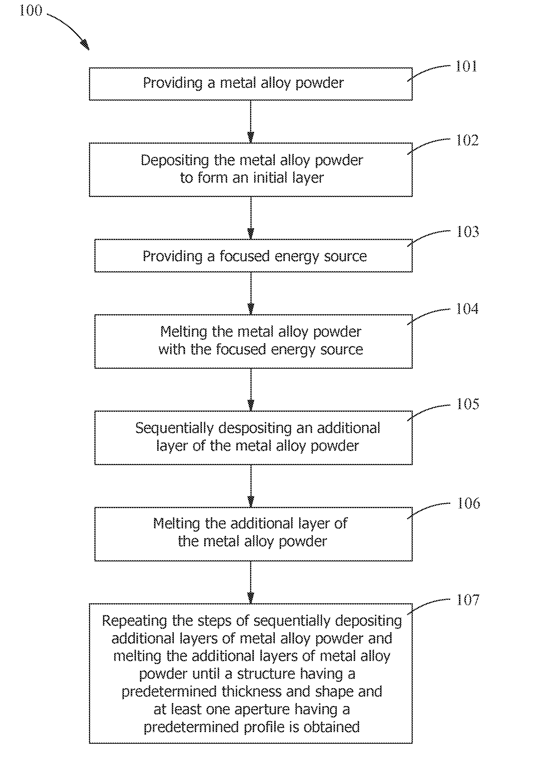
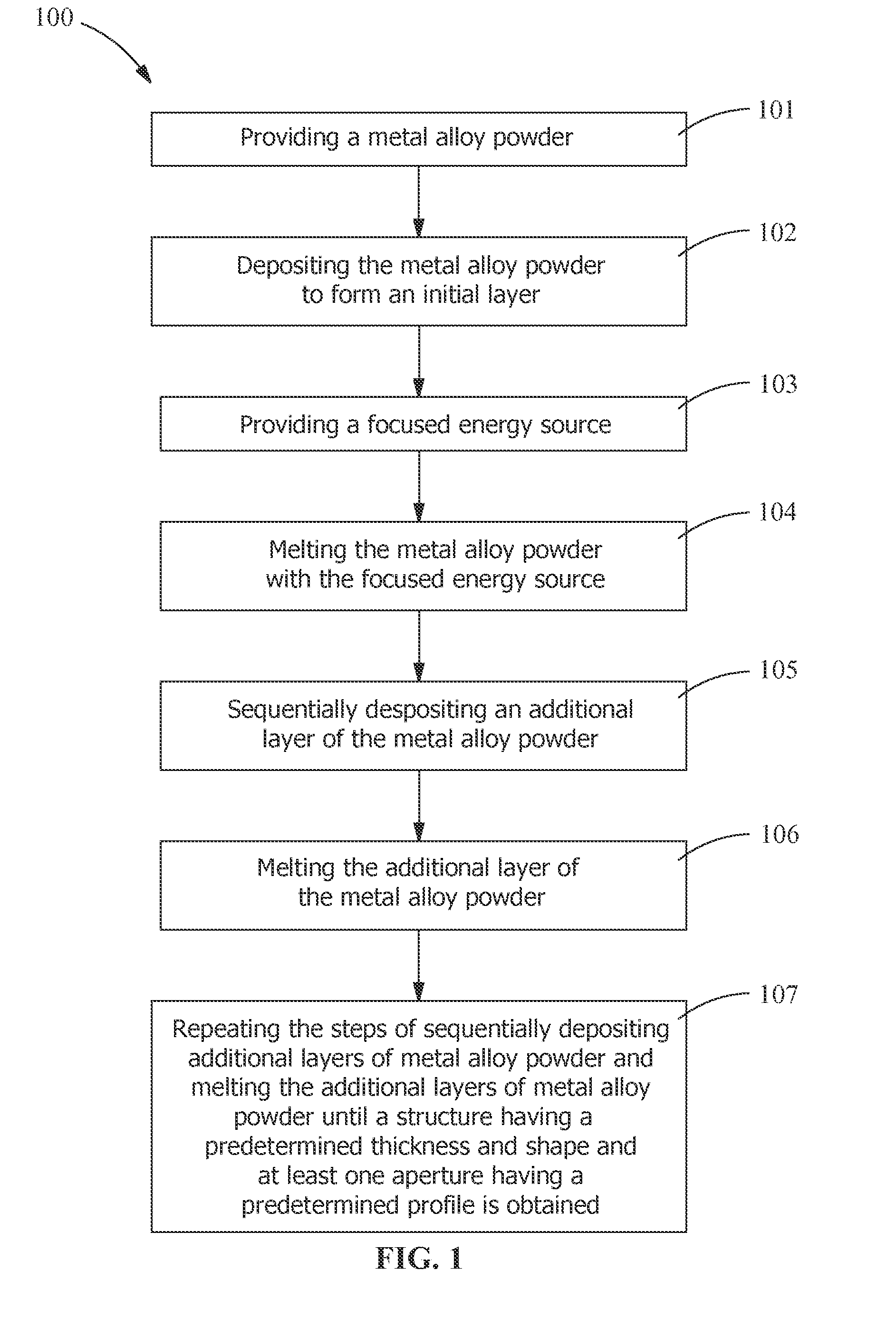
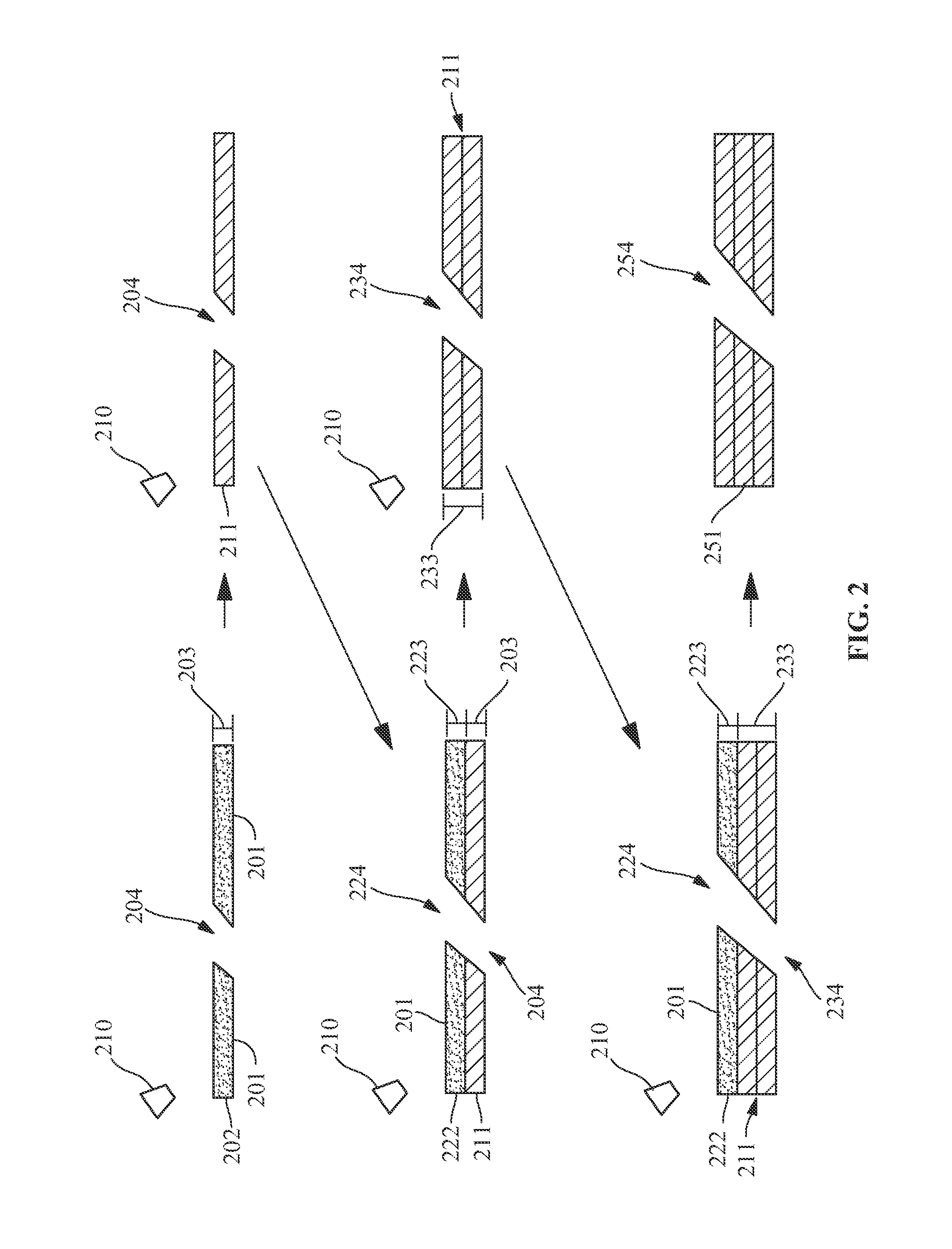
[0021]Referring to FIGS. 1-3, a method 100 of making a structure 251 with direct metal laser melting (DMLM) is provided. For example, in one embodiment, the method 100 includes making shaped cooling holes in an article. The method 100 provides any shape to the structure 251, the cooling hole in the structure 251, or any other feature in the structure 251 including an aper...


PUM

PropertyMeasurementUnit
angleaaaaaaaaaa
angleaaaaaaaaaa
angleaaaaaaaaaa

Abstract

An article and a method for making shaped cooling holes in an article are provided. The method includes the steps of depositing a metal alloy powder to form an initial layer including at least one aperture, melting the metal alloy powder with a focused energy source to transform the powder layer to a sheet of metal alloy, sequentially depositing an additional layer of the metal alloy powder to form a layer including at least one aperture corresponding to the at least one aperture in the initial layer, melting the additional layer of the metal alloy powder with the focused energy source to increase the sheet thickness, and repeating the steps of sequentially depositing and melting the additional layers of metal alloy powder until a structure including at least one aperture having a predetermined profile is obtained. The structure is attached to a substrate to make the article.

Description

STATEMENT REGARDING FEDERALLY SPONSORED RESEARCH[0001]This invention was made with government support under contract number DE-FC26-05NT42643 awarded by the Department of Energy. The government has certain rights in this invention.FIELD OF THE INVENTION[0002]The present invention is directed toward an article and a method for making an article. More specifically, the present invention is directed to an article including cooling holes and a method for making cooling holes in an article.BACKGROUND OF THE INVENTION[0003]Turbine systems are continuously being modified to increase efficiency and decrease cost. One method for increasing the efficiency of a turbine system includes increasing the operating temperature of the turbine system. To increase the temperature, the turbine system must be constructed of materials which can withstand such temperatures during continued use.[0004]In addition to modifying component materials and coatings, one common method of increasing temperature capab...

Claims


Application Information

Patent Timeline
Patent Type & Authority Applications(United States)
IPC IPC(8): B22F3/105B23K31/02B32B15/01C22C19/05
CPCB22F3/1055C22C19/057B33Y80/00B32B15/01B33Y10/00B23K31/02B22F5/10B22F7/02F01D5/18B22F10/36B22F12/41B22F10/28B22F10/64C22C19/07B22F5/009B22F7/08C23C24/106C23C28/02C23C28/022C23C28/34B23K26/342B23K35/304B23K35/3046C22C19/055C22C19/056B23K2101/001B29C64/153Y02P10/25B22F10/00
Inventor LACY, BENJAMIN, PAULSCHICK, DAVID, EDWARDKOTTILINGAM, SRIKANTH, CHANDRUDU
Owner GENERAL ELECTRIC CO
Learn More