Method of making a coil for an electrical motor

a technology of electric motor and coil, which is applied in the direction of magnets, windings, magnetic bodies, etc., can solve the problems of reducing the performance of the motor, time-consuming winding, and requiring special and expensive production equipment, so as to reduce the distance between the rotor and the stator of the motor, the thickness of the sheet structure is slightly increased, and the effect of reducing the distan

Inactive Publication Date: 2006-09-07
DANFOSS AS
View PDF4 Cites 4 Cited by
  • Summary
  • Abstract
  • Description
  • Claims
  • Application Information

AI Technical Summary

Benefits of technology

[0019] Due to resiliency of the glue, the sheet structure becomes flexible. Due to the flexibility, the sheet structure may be rolled up to form a flexible tubular coil element which can be inserted into a tubular core element, e.g. forming a stator or a rotor for an electrical motor. Preferably, the sheet structure is made in a dimension so that the length of the tubular coil element exceeds the length of the corresponding tubular core element. This allows the coil element to be arranged, e.g. coaxially inside or outside the core element to co-extend the coil element in both of its axially disposed ends. Typically, the thickness of the sheet structure is slightly increased at the area where the wire was folded during the flattening of the wire coil. Preferably, the sheet structure is rolled into a tubular coil element wherein the folds of the wire, caused by the preceding flattening of the wire coil, is located only along the axially disposed end portions of the tubular coil element, and preferably this part of the tubular coil element is located outside the tubular core element.
[0020] After insertion of the tubular coil element into the tubular core element, the coil element may be expanded radially outwardly and thus be brought into close contact with an inner surface of the core whereby the distance between the rotor and the stator of the motor can be reduced.

Problems solved by technology

The making of such a winding is, however, time consuming and requires skills and very specific and expensive production equipment.
Furthermore, this motor type has the disadvantage of cogging because of the slots.
This second motor type is easier to manufacture but, in contrary to the firstly mentioned motor type, the insertion of a tubular coil element into the tubular core element increases the distance between the core and the rotor of the motor and thus reduces the performance of the motor.
During the tilting and flattening procedure, it is difficult to avoid disorder in the helical coils and the cross-sectional shape is most often deformed whereby wires get tangled and typically some windings overlap other windings whereby the thickness of the coil increases.
Due to the increased thickness, there is a need for a larger air gap between the core and the coil, and therefore the efficiency of the motor is reduced.
The resulting distance between the tubular core element and the rotor, i.e. the thickness of the glue layer and the thickness of the coil element, is relatively large resulting in a reduced performance of the motor.

Method used


Image

  • Method of making a coil for an electrical motor
  • Method of making a coil for an electrical motor
  • Method of making a coil for an electrical motor

Examples


Embodiment Construction

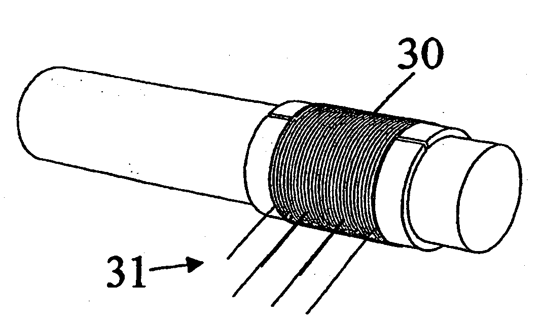
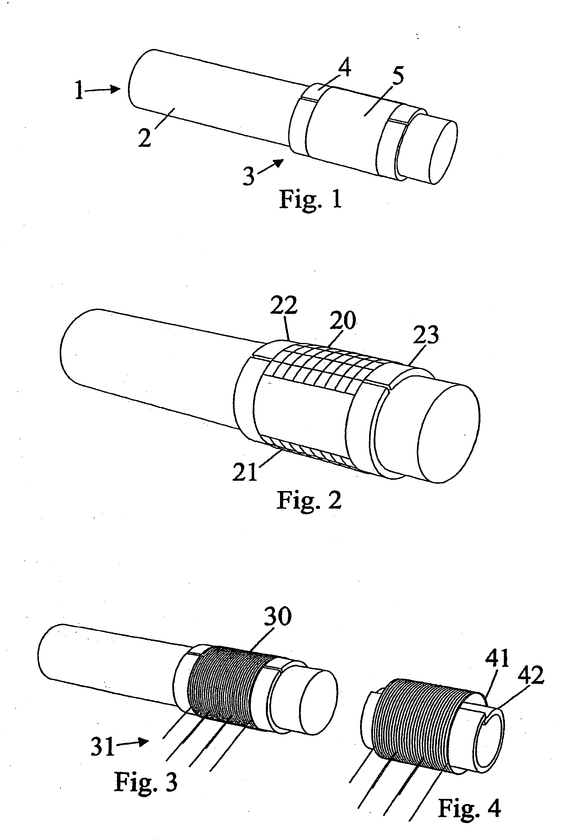
[0041]FIG. 1 shows a mandrel 1. A tension bush 3 is arranged on an outer surface of the mandrel to allow changes to the radial dimension of the mandrel for easy removal of the wire coil there from. On the outer surface 4 of the tension bush, a non-adhesive and an adhesive layer is applied in the form of a glue application tape 5 comprising a backing paper and a resilient glue material, e.g. a rubber or an acrylic material. The mandrel and the sleeve are made from a rigid material, e.g. steel, and it may in one end be connected to a driveshaft connected to power driven means for rotating the mandrel around its centre axis. The mandrel can be made with a slot for receiving a rim portion of the flexible sheet material to ease fastening of the material to the mandrel during wrapping of the sheet around the mandrel. For the same purpose, the mandrel could also be made with a plurality of small suction holes connected to a vacuum pump for maintaining the flexible sheet in place during app...


PUM

PropertyMeasurementUnit
conductiveaaaaaaaaaa
flexibleaaaaaaaaaa
resilientaaaaaaaaaa

Abstract

The invention provides a method for simplifying manufacturing of electrical motors by making a sheet with a plurality of windings of a conductive wire. The sheet is rolled into a tubular body which is inserted into a tubular stator element made from a magnetically conductive material, and pressed into contact with an inner surface thereof. According to the invention, a part of an outer surface of a mandrel is covered with a non-adhesive layer and with an adhesive layer. Subsequently, a wire is coiled onto the mandrel in contact with the adhesive layer. Due to the non-adhesive layer, the coil may easily be removed from the mandrel, and due to the adhesive layer, the windings of the coil are kept in place during a subsequent flattening of the coil. Accordingly, disorder between the windings of the coil can be avoided and a motor with an improved capacity can be manufactured more easily.

Description

CROSS REFERENCE TO RELATED APPLICATIONS [0001] This application is entitled to the benefit of and incorporates by reference essential subject matter disclosed in International Patent Application No. PCT / DK2004 / 000525 filed on Aug. 5, 2004 and Danish Patent Application No. PA 2003 01150 filed Aug. 9, 2003.FIELD OF THE INVENTION [0002] The present invention relates to a stator coil and a method of making a coil for an electrical motor of the kind comprising a stator with a tubular core and a tubular coil arranged in contact with the inner surface thereof. In particular, the invention relates to a sheet structure comprising two layers of windings which can be joined with a core of a stator or rotor to induce a magnetic field therein. The invention further relates to a sheet structure and a tubular core joined therewith. BACKGROUND OF THE INVENTION [0003] In general, electrical motors with a stator of the above mentioned kind exist. In traditional motors, the windings of the coil are ar...

Claims


Application Information

Patent Timeline
Patent Type & Authority Applications(United States)
IPC IPC(8): H01F7/06H02K3/47H02K15/04
CPCH02K3/47Y10T29/49073Y10T29/49071H02K15/0435
Inventor HANSEN, OLE
Owner DANFOSS AS
Why Eureka
Try Eureka