Three-dimensional forming apparatus and three-dimensional forming method
Inactive Publication Date: 2016-03-31
SEIKO EPSON CORP
6 Cites 33 Cited by
AI-Extracted Technical Summary
Problems solved by technology
In the three-dimensional fabricated object manufacturing method disclosed in JP-A-2008-184622, however, only some of the material layers supplied in the layered state are sintered or melted through the radiation of the light beam to be formed as a part of the fabricated object and the material layers to which the light beam is not radiated are un...
Method used
[0046]As illustrated in FIG. 1, a three-dimensional forming apparatus 100 includes a base 10, a stage 20 included to be able to be driven in the Z direction illustrated in the drawing by a driving unit (not illustrated) included in the base 10, and a robot 30 serving as a driving unit that holds a material supply unit and a heating unit to be described below and is able to move the material supply unit and the heating unit. On the stage 20, partial fabricated objects 201, 202, and 203 are formed in layer states while being formed in a three-dimensional fabricated object 200. As will be described in the formation of the three-dimensional fabricated object 200, heat energy is radiated through a laser. Therefore, to protect the stage 20 from heat, a sample plate 21 with a heat resistance property may be used so that the three-dimensional fabricated object 200 is formed on the sample plate 21. For example, by using a ceramic plate as the sample plate 21, a high heat resistance property can be obtained, reactivity to a supplied material to be sintered or melted is also low, and a change in the nature of the three-dimensional fabricated object 200 can be prevented. In FIG. 1, three layers, the partial fabricated objects 201, 202, and 203, are exemplified to facilitate the description. However, the partial fabricated objects are stacked up in the shape of the desired three-dimensional fabricated object 200.
[0052]A supply tube 70a serving as a material supply path is extended from the material supply unit 70 and is connected to the nozzle 40. The material supply unit 70 accommodates, as a supply material, a sintering material including a raw material of the three-dimensional fabricated object 200 fabricated by the three-dimensional forming apparatus 100 according to the embodiment. The sintering material which is the supply material is a mixed material of a slurry state (or a paste form) obtained by kneading, for example, an elementary powder of metals such as magnesium (Mg), iron (Fe), cobalt (Co), chrome (Cr), AL (aluminum), titanium (Ti), and nickel (Ni) which are raw materials of the three-dimensional fabricated object 200, or a mixed powder of an alloy including one or more of the metals with a solvent and a thickener serving as a binder. The average grain diameter of the metal powder is preferably equal to or less than 10 μm, the solvent is preferably a water soluble solvent, and the thickener with a hydroxyl group such as PVA (polyvinyl alcohol) or CeNF (nano-cellulose) is preferably used. For example, a thermoplastic resin such as PLA (polylactic acid), PA (polyamide), or PPS (polyphenylene sulfide) can also be used. When the thermoplastic resin is used, the nozzle 40 and the material supply unit 70 are heated so that softness of the thermop...
Benefits of technology
[0031]According to this application example, an operation and driving are performed in cooperation with the first arm, the second arm, the stage, the material supply n...
Abstract
A three-dimensional forming apparatus includes: a material supply unit that supplies a stage with a sintering material in which metal powder and a binder are kneaded; a heating unit that supplies the sintering material supplied from the material supply unit with energy capable of sintering the sintering material; and a driving unit that is able to move the material supply unit and the heating unit three-dimensionally relative to the stage, wherein the material supply unit supplies a predetermined amount of the sintering material to a desired position on the stage and the energy is supplied to the supplied sintering material from the heating unit.
Application Domain
Transportation and packagingIncreasing energy efficiency +3
Technology Topic
Material supplyMetal powder
Image
Examples
- Experimental program(5)
Example
First Embodiment
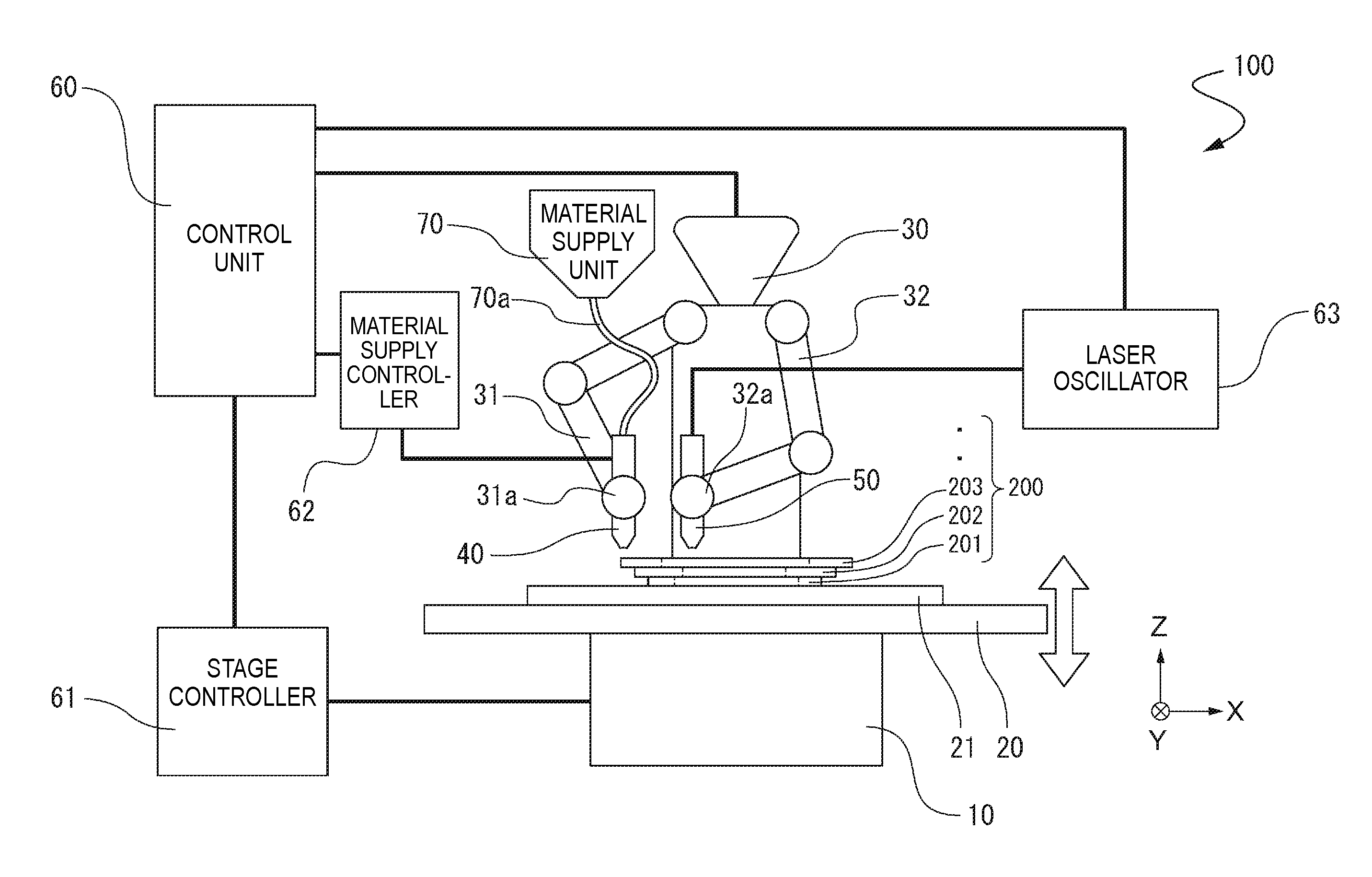
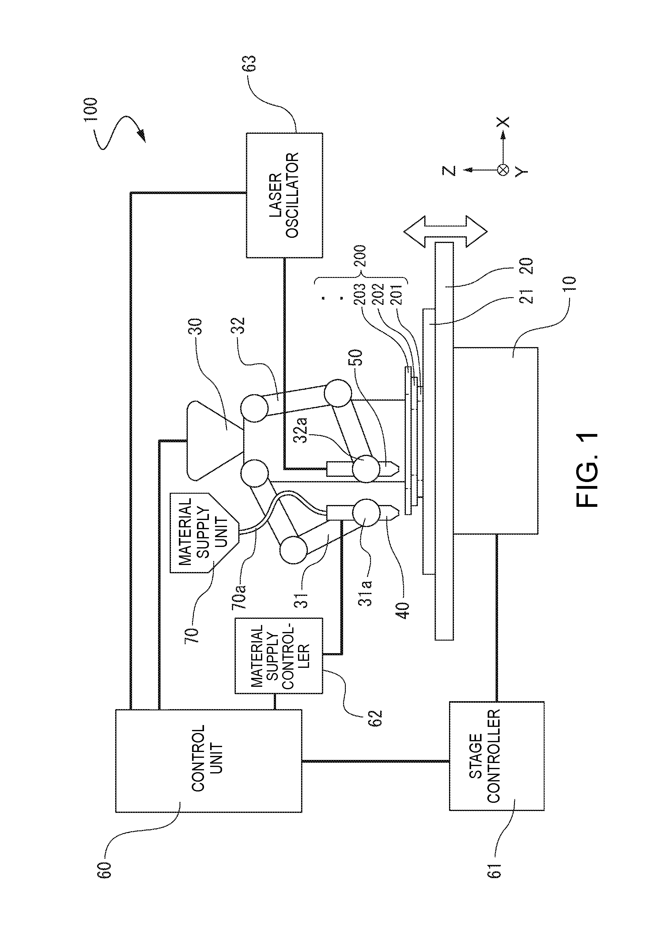
[0045]FIG. 1 is a schematic diagram illustrating the configuration of a three-dimensional forming apparatus according to a first embodiment. In the present specification, “three-dimensional forming” refers to forming a so-called stereoscopically fabricated object and includes, for example, forming a shape having a thickness even when the shape is a flat shape or a so-called two-dimensional shape.
[0046]As illustrated in FIG. 1, a three-dimensional forming apparatus 100 includes a base 10, a stage 20 included to be able to be driven in the Z direction illustrated in the drawing by a driving unit (not illustrated) included in the base 10, and a robot 30 serving as a driving unit that holds a material supply unit and a heating unit to be described below and is able to move the material supply unit and the heating unit. On the stage 20, partial fabricated objects 201, 202, and 203 are formed in layer states while being formed in a three-dimensional fabricated object 200. As will be described in the formation of the three-dimensional fabricated object 200, heat energy is radiated through a laser. Therefore, to protect the stage 20 from heat, a sample plate 21 with a heat resistance property may be used so that the three-dimensional fabricated object 200 is formed on the sample plate 21. For example, by using a ceramic plate as the sample plate 21, a high heat resistance property can be obtained, reactivity to a supplied material to be sintered or melted is also low, and a change in the nature of the three-dimensional fabricated object 200 can be prevented. In FIG. 1, three layers, the partial fabricated objects 201, 202, and 203, are exemplified to facilitate the description. However, the partial fabricated objects are stacked up in the shape of the desired three-dimensional fabricated object 200.
[0047]As illustrated in the drawing, the robot 30 is a so-called double-arm robot that includes a first arm 31 and a second arm 32. A material supply nozzle 40 (hereinafter referred to as the nozzle 40) serving as a material supply unit that supplies a sintering material which is a material of the three-dimensional fabricated object 200 is gripped or fixed to a first hand unit 31a of the first arm 31. A laser radiation device 50 serving as a heating unit is gripped or fixed to a second hand unit 32a of the second arm 32.
[0048]In the robot 30, the arms 31 and 32 include a plurality of joints (flexibility), and thus the hand units 31a and 32a can be driven three-dimensionally, that is, can be driven in the X axis direction, the Y axis direction, and the Z axis direction illustrated the drawing. In addition to operations of the arms 31 and 32, the nozzle 40 gripped or fixed to the first hand unit 31a and the laser radiation device 50 gripped or fixed to the second hand unit 32a can be moved three-dimensionally relative to the stage 20 through movement of the stage 20 included in the base 10 in the Z direction. The hand units 31a and 32a included in the arms 31 and 32 are connected to be rotatable with respect to the joints, and thus can be rotated, for example, using axes extending along the X axis, the Y axis, and the Z axis as rotation axes. In the three-dimensional forming apparatus 100, the Z axis direction is a direction along the gravity direction.
[0049]The three-dimensional forming apparatus 100 includes a control unit 60 serving as a control unit that controls the stage 20, the robot 30, the nozzle 40, and the laser radiation device 50 described above based on fabrication data of the three-dimensional fabricated object 200 output from, for example, a data output apparatus such as a personal computer (not illustrated). Although not illustrated in the drawing, the control unit 60 at least includes a driving control unit for the first arm 31 and the second arm 32 of the robot 30, a driving control unit of the stage 20, an operation control unit of the nozzle 40, and an operation control unit of the laser radiation device 50. The control unit 60 further includes a control unit driven and operated in cooperation with the robot 30, the stage 20, the nozzle 40, and the laser radiation device 50.
[0050]In regard to the stage 20 included to be able to be moved to the base 10, signals used to control movement start and stop, a movement direction, a movement amount, a movement speed, and the like of the stage 20 are generated based on control signals from the control unit 60 in a stage controller 61 and are transmitted to a driving device (not illustrated) included in the base 10 for driving.
[0051]In regard to the nozzle 40 gripped or fixed to the first hand unit 31a of the first arm 31, a signal used to control the amount of material to be supplied or the like from the nozzle 40 is generated based on a control signal from the control unit 60 in a material supply controller 62, and thus an appropriate amount of material is supplied from the nozzle 40.
[0052]A supply tube 70a serving as a material supply path is extended from the material supply unit 70 and is connected to the nozzle 40. The material supply unit 70 accommodates, as a supply material, a sintering material including a raw material of the three-dimensional fabricated object 200 fabricated by the three-dimensional forming apparatus 100 according to the embodiment. The sintering material which is the supply material is a mixed material of a slurry state (or a paste form) obtained by kneading, for example, an elementary powder of metals such as magnesium (Mg), iron (Fe), cobalt (Co), chrome (Cr), AL (aluminum), titanium (Ti), and nickel (Ni) which are raw materials of the three-dimensional fabricated object 200, or a mixed powder of an alloy including one or more of the metals with a solvent and a thickener serving as a binder. The average grain diameter of the metal powder is preferably equal to or less than 10 μm, the solvent is preferably a water soluble solvent, and the thickener with a hydroxyl group such as PVA (polyvinyl alcohol) or CeNF (nano-cellulose) is preferably used. For example, a thermoplastic resin such as PLA (polylactic acid), PA (polyamide), or PPS (polyphenylene sulfide) can also be used. When the thermoplastic resin is used, the nozzle 40 and the material supply unit 70 are heated so that softness of the thermoplastic resin is maintained. A supply property can be improved by using a silicone oil or the like as the solvent.
[0053]In regard to the laser radiation device 50 gripped or fixed to the second hand unit 32a of the second arm 32, a predetermined output laser is oscillated by the laser oscillator 63 based on a control signal from the control unit and a laser is radiated from a radiation unit (not illustrated) of the laser radiation device 50. The laser is radiated to the supply material ejected from the nozzle 40, and thus the metal powder included in the supply material is sintered or melted to be solidified. At this time, the solvent and the thickener included in the supply material simultaneously transpire by the heat of the laser. The laser used for the three-dimensional forming apparatus 100 according to the embodiment is not particularly limited. A fiber laser or a carbon dioxide laser is appropriately used since a wavelength is long and metal absorption efficiency is high. A fiber laser is more preferable since an output is high and a fabrication time can be shortened.
[0054]The supply material from the nozzle 40 is supplied along the movement path of the nozzle 40 based on fabrication data of the three-dimensional fabricated object 200 acquired from the control unit 60. For the laser radiation device 50, similarly, a movement path is formed along the movement path of the nozzle 40, that is, a supply region of the supply material, based on the fabrication data of the three-dimensional fabricated object 200 acquired from the control unit 60. The radiation of the laser from the laser radiation device 50 is preferably performed to track the supply of the material from the nozzle 40.
[0055]The tracking refers to the start of radiation of the laser from the laser radiation device 50 before the supply of the supply material from the nozzle 40 is completed at least along the shape of the partial fabricated object 201, for example, when the partial fabricated object 201 is formed. Preferably, the nozzle 40 and the laser radiation device 50 are moved for proximity tracking. A distance between the nozzle 40 and the laser radiation device 50 is appropriately set in a range in which a heat influence is not given to the supply material immediately after the supply material is ejected from a material supply port of the nozzle 40, and the distance is preferably maintained during the movement path of the nozzle 40.
[0056]In the three-dimensional forming apparatus 100 according to the first embodiment, the three-dimensional fabricated object 200 is formed in such a manner that the supply material is supplied from the nozzle 40 along the fabrication shape of the three-dimensional fabricated object 200 and is sintered or melted sequentially through the radiation of the laser from the laser radiation device 50 moved to track the nozzle 40. In the forming of the partial fabricated object 201 as an example of the forming of the partial fabricated objects 201, 202, and 203 formed in the layered state, a case is assumed in which operations of first supplying the sintering material (a material before sintering) in the shape of the partial fabricated object 201, and then radiating the laser from the laser radiation device 50 and sintering the material are performed. In the operations, there is a concern of the three-dimensional fabricated object 200 with desired quality and shape being rarely obtained due to the heat influence of the energy of the laser on an unsintered portion in a region distant from the laser radiation device 50 and a change in the nature or deformation of the supply material before sintering.
[0057]In the three-dimensional forming apparatus 100 according to the embodiment, the partial fabricated object 201 is formed in such a manner that the supply material is supplied from the nozzle 40 along the fabrication shape of the layered state of the partial fabricated object 201 of the three-dimensional fabricated object 200 and is sintered or melted sequentially through the radiation of the laser from the laser radiation device 50 moved to track the nozzle 40. Thus, it is possible to reliably form the three-dimensional fabricated object 200 including the desired partial fabricated objects in the layered state. Further, in the three-dimensional forming apparatus 100, since the material is supplied only to the regions of the shapes of the partial fabricated objects, the three-dimensional forming can be performed with a small loss of the material.
[0058]In the three-dimensional forming apparatus 100 according to the embodiment, the double-arm robot 30 has been exemplified as the movement driving unit of the nozzle 40 and the laser radiation device 50, but the invention is not limited thereto. For example, each of the nozzle 40 and the laser radiation device 50 may be driven by an articulated robot or an orthogonal robot.
Example
Second Embodiment
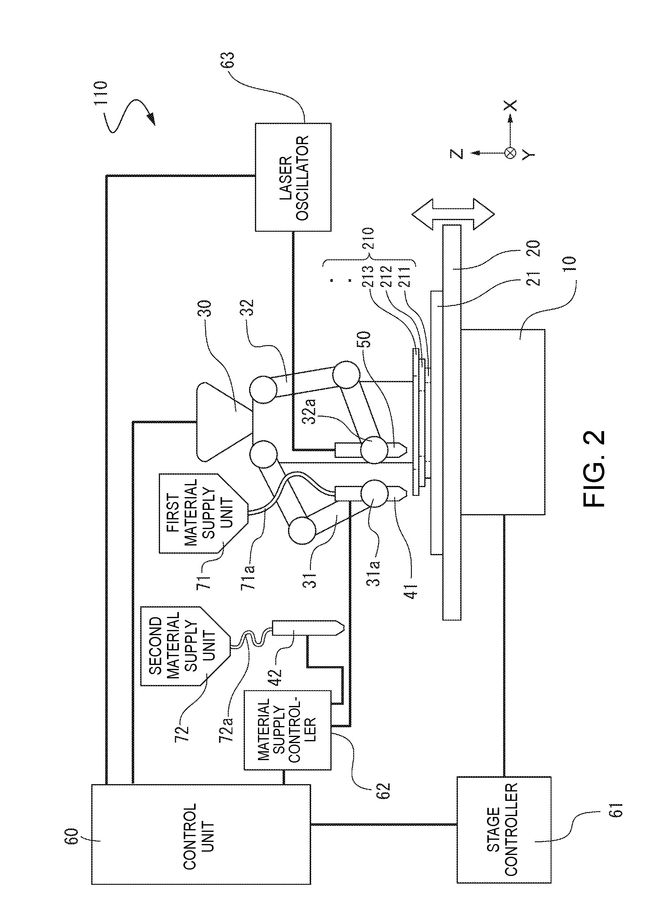
[0059]FIG. 2 is a schematic diagram illustrating the configuration of a three-dimensional forming apparatus according to a second embodiment. In a three-dimensional forming apparatus 110 illustrated in FIG. 2, a plurality of kinds of supply materials, two kinds of supply materials in the embodiment, are used compared to the three-dimensional forming apparatus 100 according to the first embodiment. The same reference numerals are given to the same constituent elements as those of the three-dimensional forming apparatus 100 according to the first embodiment, and the description thereof will be omitted.
[0060]As illustrated in FIG. 2, the three-dimensional forming apparatus 110 includes a first material supply unit 71 and a second material supply unit 72. A first supply tube 71a serving as a material supply path is extended to the first material supply unit 71 and a first nozzle 41 is connected to the end of the first supply tube 71a. Similarly, a second supply tube 72a serving as a material supply path is extended to the second material supply unit 72 and a second nozzle 42 is connected to the end of the second supply tube 72a.
[0061]The first material supply unit 71 and the second material supply unit 72 accommodate different supply materials. Based on an instruction from the control unit 60 in regard to a material to be supplied, the first hand unit 31a included in the first arm 31 selects and grips a desired nozzle between the first nozzle 41 and the second nozzle 42, so that the supply material is supplied.
[0062]In the three-dimensional forming apparatus 110 according to the embodiment, a partial fabricated object 211, a partial fabricated object 212, or a partial fabricated object 213 can be formed in such a manner that the supply material which is a sintering material supplied from one of the first material supply unit 71 and the second material supply unit 72 is sintered or melted to form a partial fabricated object, and then the supply material is supplied from the other material supply unit and is sintered or melted to form the partial fabricated object.
[0063]In this example, the two material supply units 71 and 72 have been exemplified, but the invention is not limited thereto. Three or more material supply units can be included, and thus a three-dimensional fabricated object 210 can be formed using three or more kinds of different supply materials. The material supply units 71 and 72 may accommodate the same supply material. That is, when there is a large amount of supply material or one of the material supply units is broken down, the material supply unit can be used as a preliminary material supply unit.
Example
Third Embodiment
[0064]FIGS. 3A and 3B are diagrams illustrating the configuration of a three-dimensional forming apparatus 120 according to a third embodiment. The three-dimensional forming apparatus 120 illustrated in FIG. 3A according to the embodiment has a different configuration of the heating unit from the three-dimensional forming apparatus 100 according to the first embodiment. The same reference numerals are given to the same constituent elements as those of the three-dimensional forming apparatus 100 according to the first embodiment, and the description thereof will be omitted.
[0065]As illustrated in FIG. 3A, the three-dimensional forming apparatus 120 includes a hot wind blowing mechanism 90 as a heating unit. The hot wind blowing mechanism 90 includes a compressor 91, a gas supply unit 92, and a duct 93. The hot wind blowing mechanism 90 is controlled by a hot wind blowing mechanism controller 64 connected to the control unit 60.
[0066]The compressor 91 includes a compression unit compressing a gas (not illustrated) at high pressure and supplies the gas compressed at the high pressure by the compression unit to the gas supply unit 92. An inert gas capable of preventing generation of a change in the nature of the material at the time of heating of the supply material is preferably used as the gas. The duct 93 is disposed in close proximity to the gas supply unit 92. The duct 93 is connected to the compressor 91, absorbs a supply gas G ejected to the supply material from the gas supply unit 92 and a transpired gas of the solvent and the thickener included in the supply material transpired by the heated supply gas G, and exhausts the supply gas G and the transpired gas to the outside via the compressor 91 or sends the supply gas G and the transpired gas to an inert gas recovery unit (not illustrated).
[0067]As illustrated in FIG. 3B which is a partial expanded view of a portion A illustrated in FIG. 3A, the hot wind blowing mechanism 90 includes the gas supply unit 92 so that a supply direction of the gas G supplied from the gas supply unit 92 is directed to the downstream side in a material supply direction F when a direction indicated by an illustrated arrow in which the supply material is moved while being supplied from the nozzle 40 is the material supply direction F. Thus, it is possible to prevent the supply material from being heated at a position other than a position at which predetermined sintering or melting is performed, and it is possible to avoid wrong fabrication.
[0068]FIG. 4A is a schematic sectional view illustrating the gas supply unit 92. As illustrated in FIG. 4A, the gas supply unit 92 includes at least a heat-resistant syringe 92a, a core 92b, a heater coil 92c wound around the core 92b, and a temperature sensor 92d. For example, the heat-resistant syringe 92a is formed in a cylindrical shape such as a circular cylindrical shape using heat-resistant glass or heat-resistant metal. A high-pressure gas is introduced inside the heat-resistant syringe 92a from the compressor 91.
[0069]The core 92b is arranged along the central axis of the heat-resistant syringe 92a and the heater coil 92c generating heat when a current flows in the core 92b from an external power source (not illustrated) is wound around the core 92b. The high-pressure gas introduced inside the heat-resistant syringe 92a is heated by the heater coil 92c generating the heat and is ejected as a hot wind from an ejection port 92e formed at the proximal end of the heat-resistant syringe 92a.
[0070]The temperature of the ejected hot wind is detected by the temperature sensor 92d disposed on the side of the ejection port 92e of the core 92b and the strength of the current flowing in the heater coil 92c is controlled, so that the hot wind with a desired temperature can be generated. The ejection port 92e preferably has a shape illustrated in FIG. 4B or 4C illustrating a cross-sectional surface of a portion taken along the line B-B′ illustrated in FIG. 4A so that the generated hot wind is blown and concentrated on the supply material. FIG. 4B illustrates a circular opening by which the hot wind can be further concentrated and FIG. 4C illustrates a track-shaped opening by which the hot wind can be blown more widely.
PUM
Property | Measurement | Unit |
Composition | ||
Energy |
Description & Claims & Application Information
We can also present the details of the Description, Claims and Application information to help users get a comprehensive understanding of the technical details of the patent, such as background art, summary of invention, brief description of drawings, description of embodiments, and other original content. On the other hand, users can also determine the specific scope of protection of the technology through the list of claims; as well as understand the changes in the life cycle of the technology with the presentation of the patent timeline. Login to view more.
Similar technology patents
Voltage mode pwmff-pfm/skip combo controller
Owner:MICRO DC
Thin-film solar cell and fabrication method thereof
Owner:LG ELECTRONICS INC
Classification and recommendation of technical efficacy words
- high efficiency
Emissive materials for organic light emitting devices
Owner:UNIV OF SOUTHERN CALIFORNIA +1
Organic electroluminescent device
Owner:IDEMITSU KOSAN CO LTD