Automated assembly apparatus, automated assembly system and automated assembly method
a technology of automatic assembly and assembly method, which is applied in the direction of assembly machines, metal-working apparatus, program-controlled manipulators, etc., can solve the problems of reducing assembly accuracy and achieve the effect of accurate assembly operation
- Summary
- Abstract
- Description
- Claims
- Application Information
AI Technical Summary
Benefits of technology
Problems solved by technology
Method used
Image

Examples
first embodiment
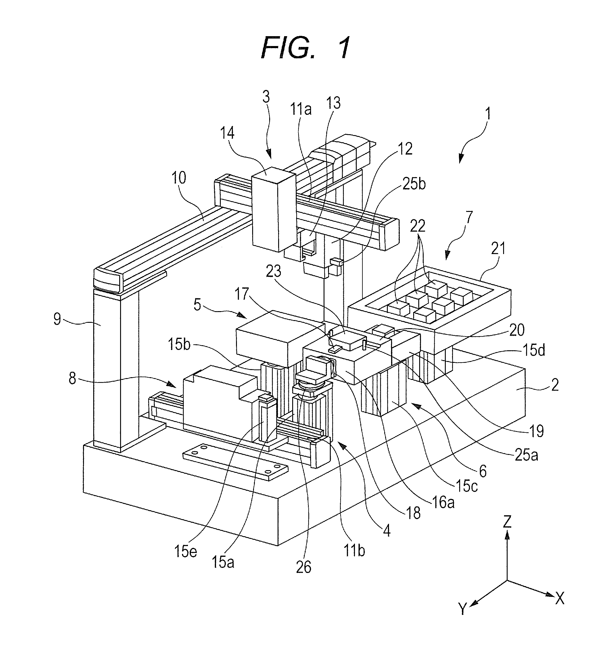
[0032]As a basic embodiment to which the present invention is applied, a first embodiment is hereinafter specifically described with reference to FIG. 1. In the diagrams, the same portions are indicated by the same symbols.
[0033]FIG. 1 is a schematic perspective view of an automated assembly method and an automated assembly apparatus according to the present invention. The automated assembly apparatus 1 includes an assembly robot 3 capable of moving in a horizontal plane, a first workbench unit (holding unit) 4, a second workbench unit 5, a positioning unit 6, a supply unit 7 and a screw supplying unit 8, which are arranged on a base 2.
[0034]The supply unit 7 includes a supply pallet 21 that contains at least one assembly component 22 in a manner capable of supplying the component. The assembly component 22 is gripped by an after-mentioned assembly hand 12 from the supply pallet 21.
[0035]The assembly robot 3 includes a Y-axis movement unit, an X-axis movement unit (first X-axis move...
second embodiment
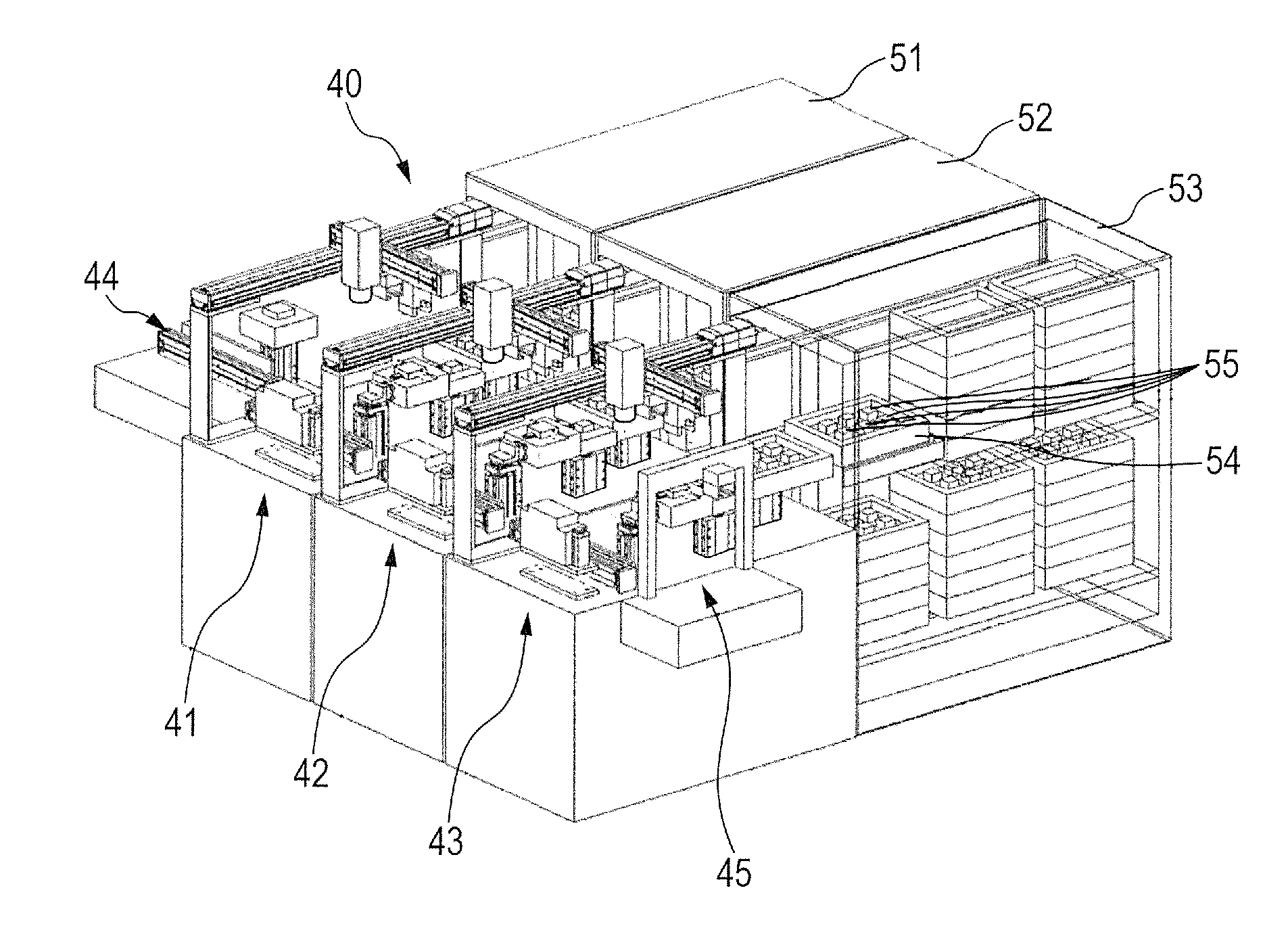
[0063]As illustrated in FIG. 3, as with the first aspect, an automated assembly apparatus of a second embodiment includes: an assembly robot that does not include a drive unit in the Z-axis direction but includes drive units in the X-axis direction and the Y-axis direction; and a workbench unit that includes a Z-axis drive unit. As to the automated assembly apparatus of the second embodiment, multiple automated assembly apparatuses can be arranged to be used as an automated assembly system. The automated assembly system 40 where three automated assembly apparatuses 41, 42 and 43 are arranged and used is hereinafter described.
[0064]The automated assembly system 40 includes the automated assembly apparatuses 41, 42 and 43, and a stockers 51, 52 and 53 that stock components. Each of the stockers 51, 52 and 53 includes multiple supply pallets 54 that each store multiple assembly components 55.
[0065]In the automated assembly system 40, an assembly target component is fed from a feeding s...
third embodiment
[0088]Next, a third embodiment according to the present invention is specifically described with reference to FIGS. 6A to 6E. Automated assembly apparatuses 41a and 42a according to the third embodiment are the same as the automated assembly apparatuses 41 and 42 described in the second embodiment, except for after-mentioned linear cylinders 133 and 233 and regulation units 134 and 234.
[0089]FIG. 6A illustrates a state where an assembly target component 123 having been subjected to assembly operations in the automated assembly apparatus 41a is mounted on a workbench 116a of the automated assembly apparatus 41a.
[0090]Next, in FIG. 6B, the second X-axis movement unit 111 of the automated assembly apparatus 41a extends in a direction toward the automated assembly apparatus 42a to thereby cause the workbench 116a of the automated assembly apparatus 41a to enter the inside of the automated assembly apparatus 42a. Alternatively, the second X-axis movement unit 111 may be configured to be...
PUM
| Property | Measurement | Unit |
|---|---|---|
| angle | aaaaa | aaaaa |
| angle | aaaaa | aaaaa |
| speed | aaaaa | aaaaa |
Abstract
Description
Claims
Application Information
 - R&D
- Intellectual Property
- Life Sciences
- Materials
- Tech Scout
- Unparalleled Data Quality
- Higher Quality Content
- 60% Fewer Hallucinations
Browse by: Latest US Patents, China's latest patents, Technical Efficacy Thesaurus, Application Domain, Technology Topic, Popular Technical Reports.
© 2025 PatSnap. All rights reserved.Legal|Privacy policy|Modern Slavery Act Transparency Statement|Sitemap|About US| Contact US: help@patsnap.com