
Liquid discharge apparatus

Active Publication Date: 2016-03-31
BROTHER KOGYO KK
View PDF1 Cites 0 Cited by
  • Summary
  • Abstract
  • Description
  • Claims
  • Application Information

AI Technical Summary

Benefits of technology

The patent is about a device that cleans windshields and other surfaces. The device has a flexible wiper that is inserted into a slit in a wiper cleaner. A support member holds the wiper in place, but sometimes the wiper gets caught or scratched by the slit, which causes it to bend or deform. This interference can result in poor cleaning performance. However, there is a space between the wiper and the wiper cleaner that allows the wiper to move smoothly through the slit. This space is created by the guide pieces, which help regulate the bending and deformation of the wiper. This design prevents damage to the wiper while still maintaining effective cleaning.

Problems solved by technology

The above ink-jet printer, however, has the following problems.
This prevents the wiper from passing through the slit smoothly, and further the wiper or the wiper cleaner is liable to get damaged.
Further, the upper part of the wiper cleaner is practically undeformable, because the wiper cleaner is accommodated in the support member with the upper part of the wiper clear compressed.
Thus, when the wiper having flexibility is inserted into the slit of the wiper cleaner, the wiper may be caught or scratched by the slit.
Thus, when the wiper is inserted into the slit of the wiper cleaner, the front end of the wiper may be caught or scratched by the entrance of the slit of the wiper cleaner.
This prevents the wiper from passing through the slit smoothly, and the wiper or the wiper cleaner is liable to get damaged.

Method used


Image

  • Liquid discharge apparatus
  • Liquid discharge apparatus
  • Liquid discharge apparatus

Examples


first embodiment

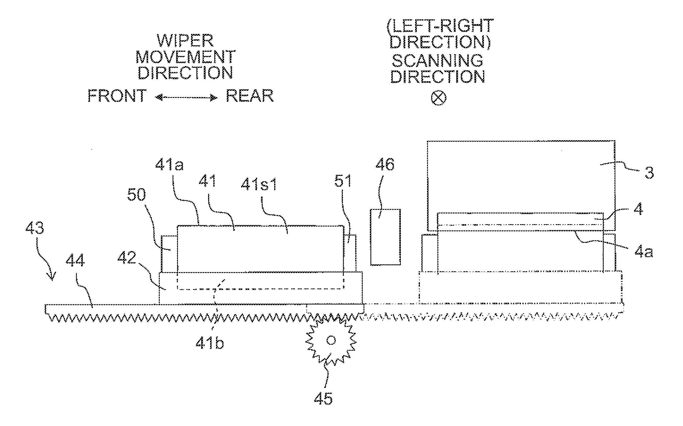
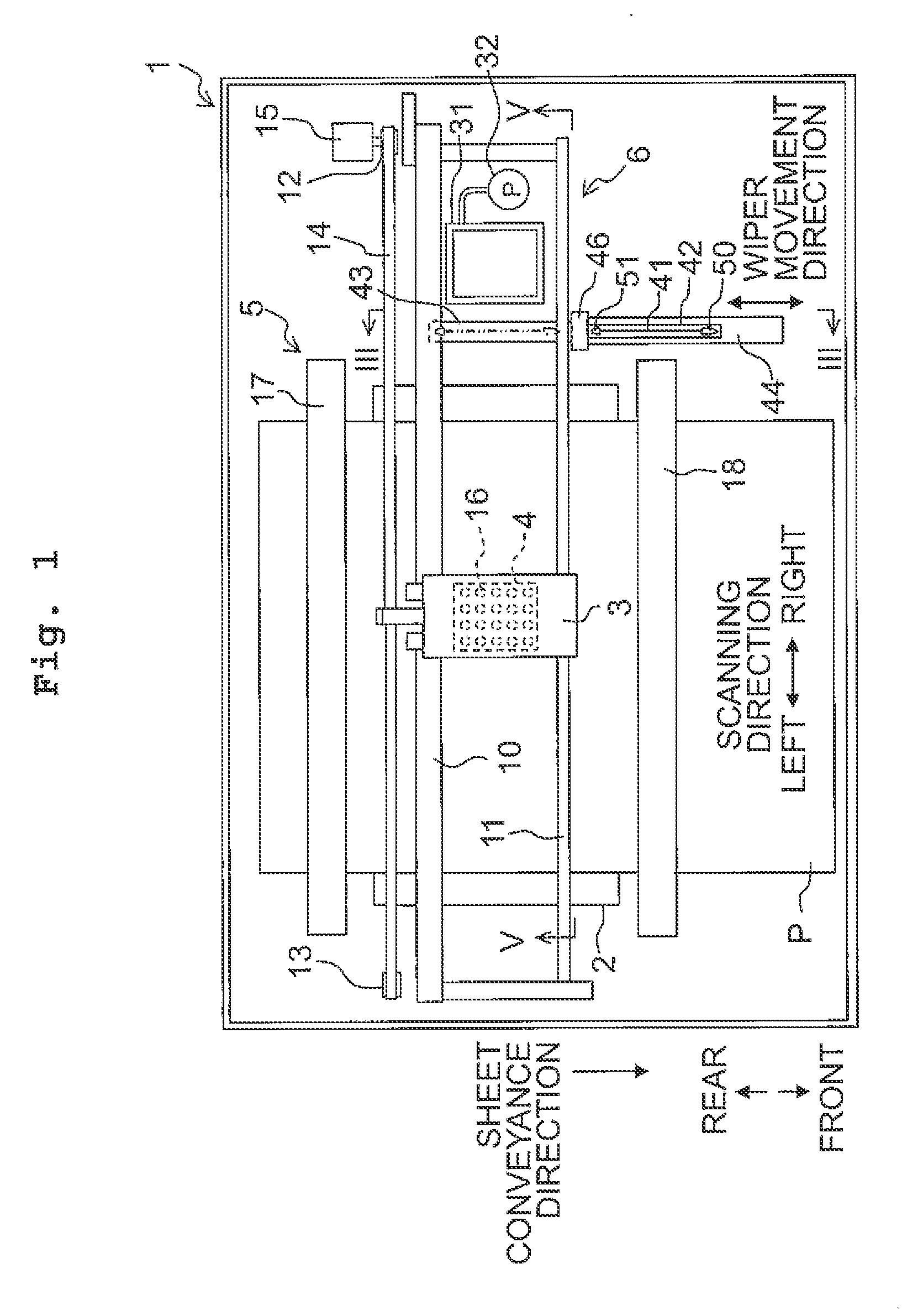
[0099]Next, an explanation will be made about the first embodiment of the present teaching. FIG. 1 is a schematic plan view depicting an ink-jet printer according to the first embodiment. In the following, the frontward direction (front side), the rearward direction (rear side), the leftward direction (left side), and the rightward direction (right side) are defined as indicated in FIG. 1, and the direction perpendicular to the paper surface of FIG. 1 is defined as the up-down direction. These definitions are appropriately used in the following description.

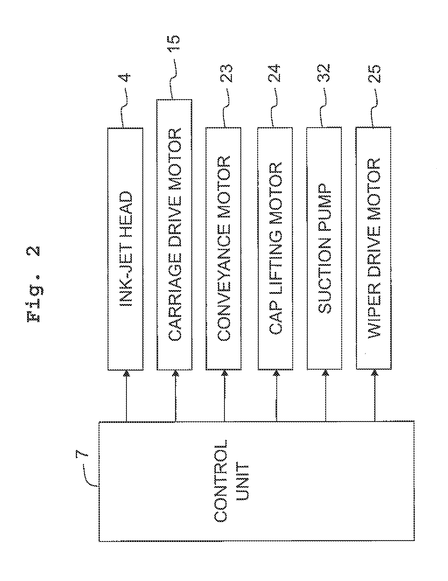
[0100]As depicted in FIG. 1, an ink-jet printer 1 (a liquid discharge apparatus of the present teaching) includes a platen 2 on which a recording sheet P is placed, a carriage 3 which is reciprocatively movable in a scanning direction (left-right direction) parallel to the platen 2, an ink-jet head 4 (a liquid discharge head of the present teaching) which is carried on the carriage 3, a conveyance mechanism 5 which conveys the rec...

modified embodiments of first embodiment

[0128]Although the first embodiment of the present teaching has been explained above, the present teaching is not restricted to the first embodiment and various changes may be made within the scope of the claims. Further, the modified embodiments as described later can be performed by appropriately combining them.

[0129]In the first embodiment, two space expansion parts 50, 51 are disposed near the front and rear ends of the wiper 41 but do not to make contact therewith, respectively. One or both of two space expansion parts 50, 51, however, may be brought into contact with the front end and / or rear end of the wiper 41 in the front-rear direction.

[0130]For example, like space expansion parts 150, 151 depicted in FIG. 8, the lengths of the space expansion parts 150, 151 in the up-down direction may be the same as or longer than the length, of the wiper 41, ranging from the upper surface of the wiper holder 42 to the upper end 41a (the length from the lower end 41b to the upper end 41a...

second embodiment

[0147]Next, an explanation will be made about the second embodiment of the present teaching. The constitutive parts or components, which are the same as or equivalent to those of the first embodiment, are designated by the same reference numerals, any explanation of which will be omitted as appropriate. As depicted in FIG. 17, an ink-jet printer 1001 (a liquid discharge apparatus of the present teaching) includes a platen 2 on which a recording sheet P is placed, a carriage 3 which is reciprocatively movable in a scanning direction (left-right direction) parallel to the platen 2, an ink-jet head 4 (a liquid discharge head of the present teaching) which is carried on the carriage 3, a conveyance mechanism 5 which conveys the recording sheet P in a sheet conveyance direction (frontward direction) perpendicular to the scanning direction, a maintenance unit 1006 which performs various maintenance operations to maintain and recover the liquid discharge performance of the ink-jet head 4, ...


PUM


Abstract

There is provided a liquid discharge apparatus, including: a liquid discharge head; a wiper; a wiper cleaner cleaning a liquid adhering to a first surface of the wiper and including a first contact part, which makes contact with the first surface of the wiper, and a second contact part, which is disposed to face the first contact part and makes contact with the second surface of the wiper; a movement mechanism moving the wiper and the wiper cleaner relative to each other, and a space expansion part expanding a space between the first contact part and the second contact part.

Description

CROSS REFERENCE TO RELATED APPLICATION[0001]The present application claims priorities from Japanese Patent Application Nos. 2014-202443, 2014-202544, 2014-202545, and 2014-202546 filed on Sep. 30, 2014, the disclosures of which are incorporated herein by reference in its entirety.BACKGROUND[0002]1. Field of the Invention[0003]The present teaching relates to a liquid discharge apparatus which discharges liquid.[0004]2. Description of the Related Art[0005]As a liquid discharge apparatus which discharges liquid onto a discharge target medium from liquid discharge ports formed on a liquid discharge surface of a liquid discharge head, there is known an ink-jet printer which performs printing on a recording sheet by discharging ink from an ink-jet head. The ink-jet printer wipes off foreign matters, such as ink adhering to an ink discharge surface, with a wiper made of rubber and the like. For example, the ink-jet printer may include a wiper cleaner being made of sponge and the like and h...

Claims


Application Information

Patent Timeline
IPC IPC(8): B41J2/165
CPCB41J2/16535B41J2/16541B41J2/16538
Inventor KUNO, DAISUKEHIGUCHI, RIE
Owner BROTHER KOGYO KK
Learn More