Electrical component mounting structure for saddle-riding type vehicle

a technology of electric components and mounting structures, which is applied in the direction of transportation and packaging, cycle equipment, cycle equipment, etc., can solve the problems of excessively high level, limited space for disposing electrical components, and difficult to dispose of electrical components, so as to reduce the size and weight reduce the size and weight, and prevent excessive stiffness of the vehicle body frame

Inactive Publication Date: 2016-03-31
HONDA MOTOR CO LTD
View PDF7 Cites 4 Cited by
  • Summary
  • Abstract
  • Description
  • Claims
  • Application Information

AI Technical Summary

Benefits of technology

[0012]In the present invention, the power unit includes the crankcase and the cylinder portion that protrudes from the crankcase, and the first ECU is disposed, in a side view, anterior to the left and right pivot frames, posterior to the cylinder portion, and above the crankcase. These arrangements allow the first ECU to be disposed by effectively using a dead space created, in the side view, between the power unit and the pivot frames.
[0013]The ECU suspension member that supports the first ECU includes the pair of left and right suspension stays extending forwardly from the left and right pivot frames and the pair of left and right cross members extending inwardly in the vehicle width direction from the left and right suspension stays, respectively, and the first ECU is supported in a condition of extending across the left and right cross members. The first ECU is thus supported without the left and right pivot frames being directly connected with, for example, a part that forms part of the vehicle body frame, such as a cross member. Thus, the size of the vehicle body frame can be reduced to achieve reduction in size and weight and the stiffness of the vehicle body frame can be prevented from increasing excessively. This can achieve improved vehicle running performance, for example, turning performance.
[0014]The cross members are each plate-shaped and each have thinning holes formed at least in part thereof. This allows stiffness of the ECU suspension member to be made appropriate. Thus, the stiffness of the vehicle body frame can be prevented from becoming excessively high for the improved vehicle turning performance. Additionally, weight of the cross member can be reduced.
[0015]Because the first ECU is elastically supported by the cross members, stiffness of a connecting portion including the ECU suspension member and the first ECU and connecting between the left and right pivot frames can be made appropriate. Thus, the vehicle turning performance can be improved. Furthermore, a large external force can be prevented from being transmitted from the left and right pivot frames to the first ECU via the ECU suspension member, so that the first ECU can be protected.
[0016]The left and right suspension stays support the second ECU separate from the first ECU, and the second ECU is disposed posterior to the first ECU. Thus, the first ECU and the second ECU can be collectively disposed. This enables an even more effective use of the dead space created between the power unit and the pivot frames.
[0017]Furthermore, the first ECU and the second ECU are disposed posterior to the fuel tank supported by the main frames and the guide portion formed at a rear portion of the fuel tank is oriented such that the airflow is supplied to the first ECU and the second ECU. The guide portion of the fuel tank thus allows the first ECU and the second ECU to be cooled by the airflow blown thereagainst, so that the first ECU and the second ECU can be disposed close to the power unit.

Problems solved by technology

A space around the engine may be a possible candidate for the dead space; however, a thermal effect needs to be considered before the dead space around the engine can be properly used and it has been considered difficult to dispose the electrical component at a position near the engine.
The electrical component disposition structure in the known art, however, has a limited space for disposing the electrical components and requires the addition of, for example, a cross member separate from the bridge in order to support the electrical components.
Providing the separate cross member or the like increases stiffness of the entire vehicle body frame to an excessively high level, thus unfortunately reducing vehicle running performance including turning performance.

Method used


Image

  • Electrical component mounting structure for saddle-riding type vehicle
  • Electrical component mounting structure for saddle-riding type vehicle
  • Electrical component mounting structure for saddle-riding type vehicle

Examples


first embodiment

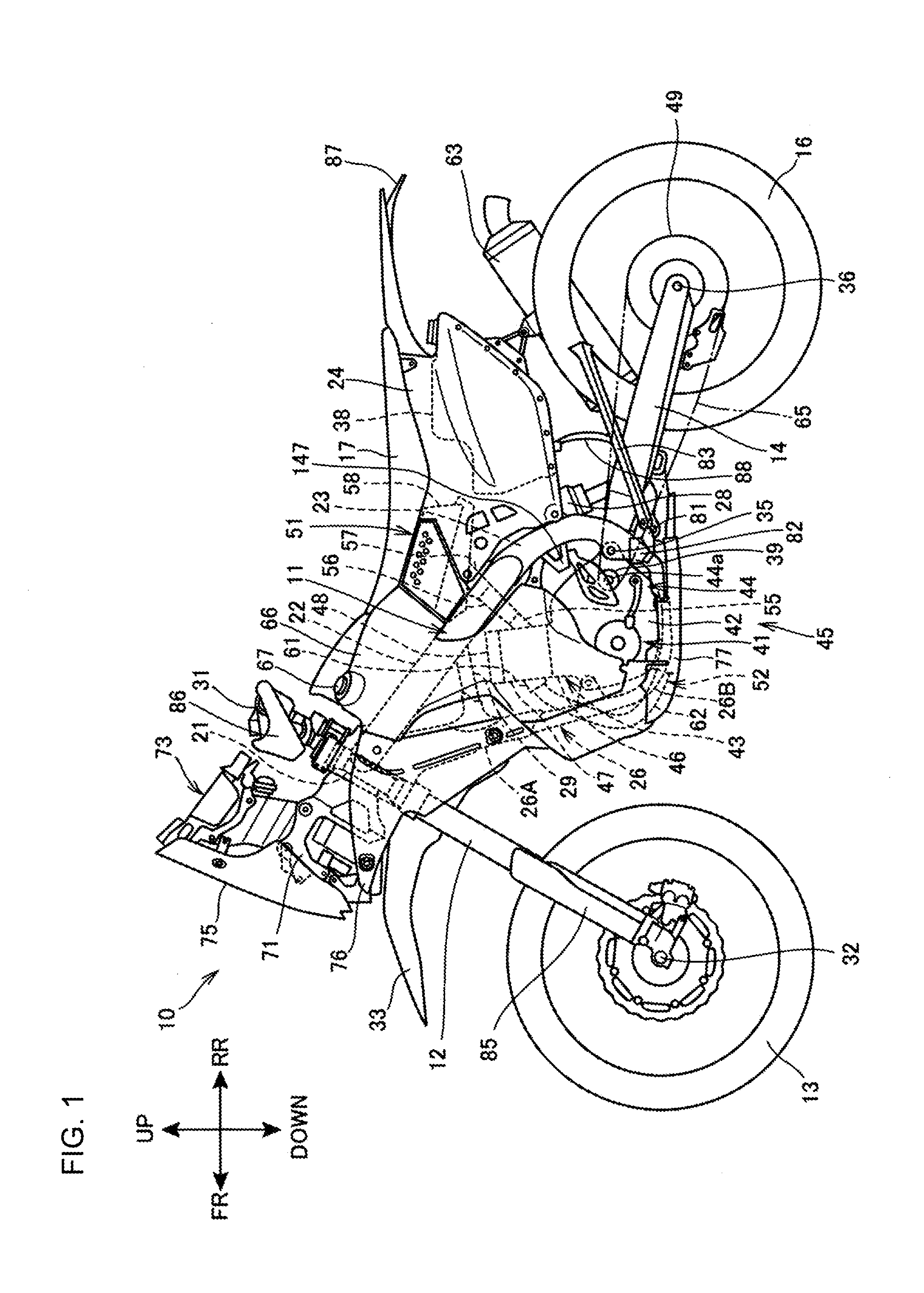
[0028]FIG. 1 is a left side elevational view showing a motorcycle 10 including an electrical component mounting structure according to the present invention.

[0029]The motorcycle 10 is a saddle-riding type vehicle including a vehicle body frame 11, a front wheel 13, a rear wheel 16, and a seat 17. The front wheel 11 is supported via a front fork 12 at a front end portion of the vehicle body frame 11. The rear wheel 16 is supported via a swing arm 14 at a lower portion of the vehicle body frame 11. The seat 17 is supported at a rear portion of the vehicle body frame 11.

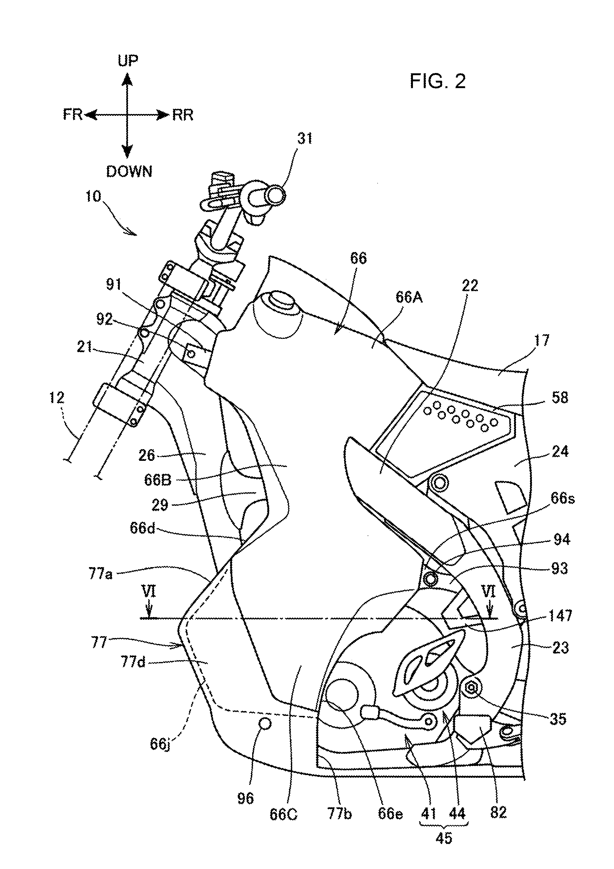
[0030]The vehicle body frame 11 assumes a framework of the motorcycle 10, including a head pipe 21, a pair of left and right main frames 22, a pair of left and right pivot frames 23, a rear frame 24, and a down frame 26.

[0031]The head pipe 21 constitutes the front end portion of the vehicle body frame 11. The front fork 12 is steerably supported on the head pipe 21. A handlebar 31 is mounted at an upper end portion of t...

second embodiment

[0094]FIG. 8 is a view showing the first ECU 175 and the second ECU 176, and the parts therearound in the second embodiment, as viewed from a direction identical to the direction in which FIG. 5 is viewed.

[0095]The recessed portion 174b has a bottom wall 174g having a substantially box shape. The bottom wall 174g includes a pair of left and right ECU mounting portions 174h and a pair of band hooks 174j and 174k. The ECU mounting portions 174h protrude rearwardly so that the second ECU 176 can be mounted thereon. The pair of band hooks 174j and 174k provides catches onto which both ends of a rubber band 179 that holds the second ECU 176 in place can be hooked.

[0096]The suspension stays 173 and the ECU bracket 174 are each formed from a plate that is bent into a corresponding shape, thus having low stiffness. The suspension stays 173 and the ECU bracket 174 thus can improve, for example, vehicle turning performance. In addition, both the first ECU 175 (see FIG. 7) and the second ECU 1...


PUM


Abstract

An electrical component mounting structure for a motorcycle includes a vehicle body frame. The vehicle body frame includes: main frames extending downwardly toward rear from a head pipe, the main frames for suspending a power unit; and pivot frames extending downward from rear ends of the main frames to be disposed at left and right in a vehicle width direction. An electrical component including a first ECU is supported in this electrical component mounting structure. In this electrical component mounting structure, the power unit includes a crankcase and a cylinder portion that protrudes from the crankcase, and the first ECU is disposed, in a side view, anterior to the left and right pivot frames, posterior to the cylinder portion, and above the crankcase.

Description

FIELD OF THE INVENTION[0001]The present invention relates to an electrical component disposition structure for a saddle-riding type vehicle in which electrical components are disposed in a dead space in a vehicle body.BACKGROUND OF THE INVENTION[0002]A known structure includes a body frame connected to ends of a pair of left and right main frames, a curved bridge that protrudes upwardly and extends across left and right connections between the main frames and the body frame, and an engine control unit (ECU) disposed inside an internal space of the bridge (see, for example, Japanese Patent Laid-Open No. 2011-912).SUMMARY OF THE INVENTION[0003]In motorcycles, however, the position at which the electrical component, such as the engine control unit, is disposed is fixed after positions at which other components, such as a vehicle body frame, an engine, and a rear cushion are disposed are fixed. This requires that the electrical component be disposed effectively within a limited space (d...

Claims


Application Information

Patent Timeline
Patent Type & Authority Applications(United States)
IPC IPC(8): B62K19/40B62J35/00B62J99/00B62K11/04
CPCB62K19/40B62K11/04B62J2099/0013B62J99/00B62J35/00B62K19/30B62J45/20B62J45/00
Inventor SASAKI, TAKASHI
Owner HONDA MOTOR CO LTD
Why Eureka
Try Eureka