Oil pump structure

a technology of oil pump and oil pump, which is applied in the direction of liquid fuel engines, machines/engines, rotary piston liquid engines, etc., can solve the problems of repeated increase and decrease of oil pressure, and achieve the effect of suppressing the slight vibration of the oil pump operation, reducing noise and/or vibration, and increasing control hydraulic pressur

Inactive Publication Date: 2016-03-31
YAMADA SEISAKUSHO KK
View PDF10 Cites 10 Cited by
  • Summary
  • Abstract
  • Description
  • Claims
  • Application Information

AI Technical Summary

Benefits of technology

[0014]The present invention comprises: an oil pump in which a capacity variation operation is carried out by applying a control hydraulic pressure to the first hydraulic control chamber and the second hydraulic control chamber; a hydraulic control valve having a valve operating oil passage, a first inflow passage and a second inflow passage by which oil discharged from the oil pump flows in, a first outflow passage by which oil is sent to the first hydraulic control chamber, and a second outflow passage by which oil is sent to the second hydraulic control chamber; and a solenoid valve which switches the valve operating oil passage and the interior of a spool valve body passage between a communicated and shut-off state. By means of the hydraulic control valve, a control hydraulic pressure is applied at all times to the first hydraulic control chamber, and the control hydraulic pressure is increased and decreased in the second hydraulic control chamber, whereby it is possible to reduce noise and/or vibration in the event of variation in the capacity of the oil pump.
[0015]Furthermore, the axial-direction dimension of the intermediate valve section in the spool valve body in the hydraulic control valve is larger than the axial-direction dimension of the second outflow passage. Therefore, the intermediate valve...

Problems solved by technology

Moreover, the oil pressure repeatedly increases and ...

Method used


Image

  • Oil pump structure
  • Oil pump structure
  • Oil pump structure

Examples


Embodiment Construction

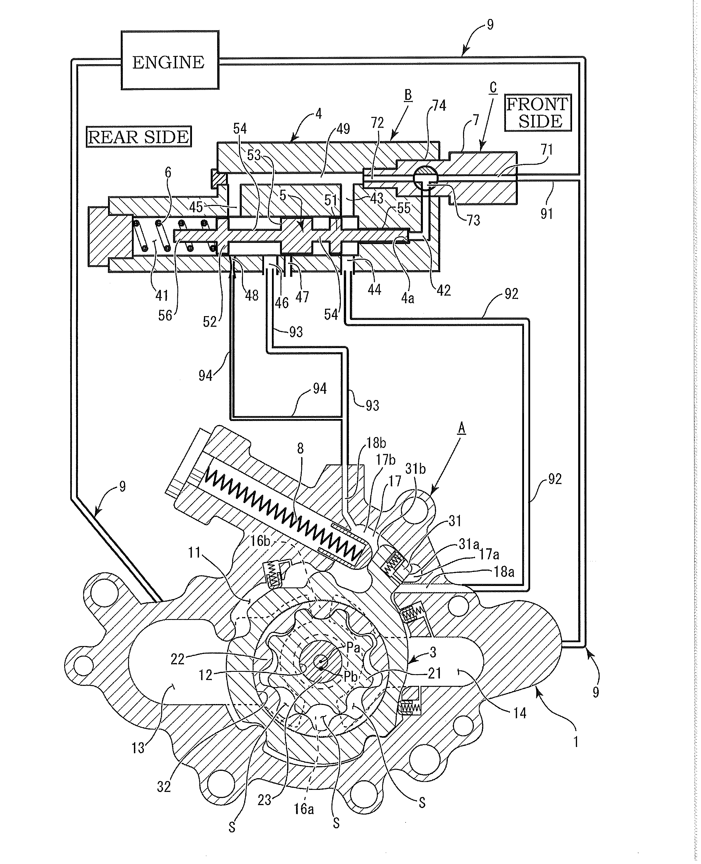
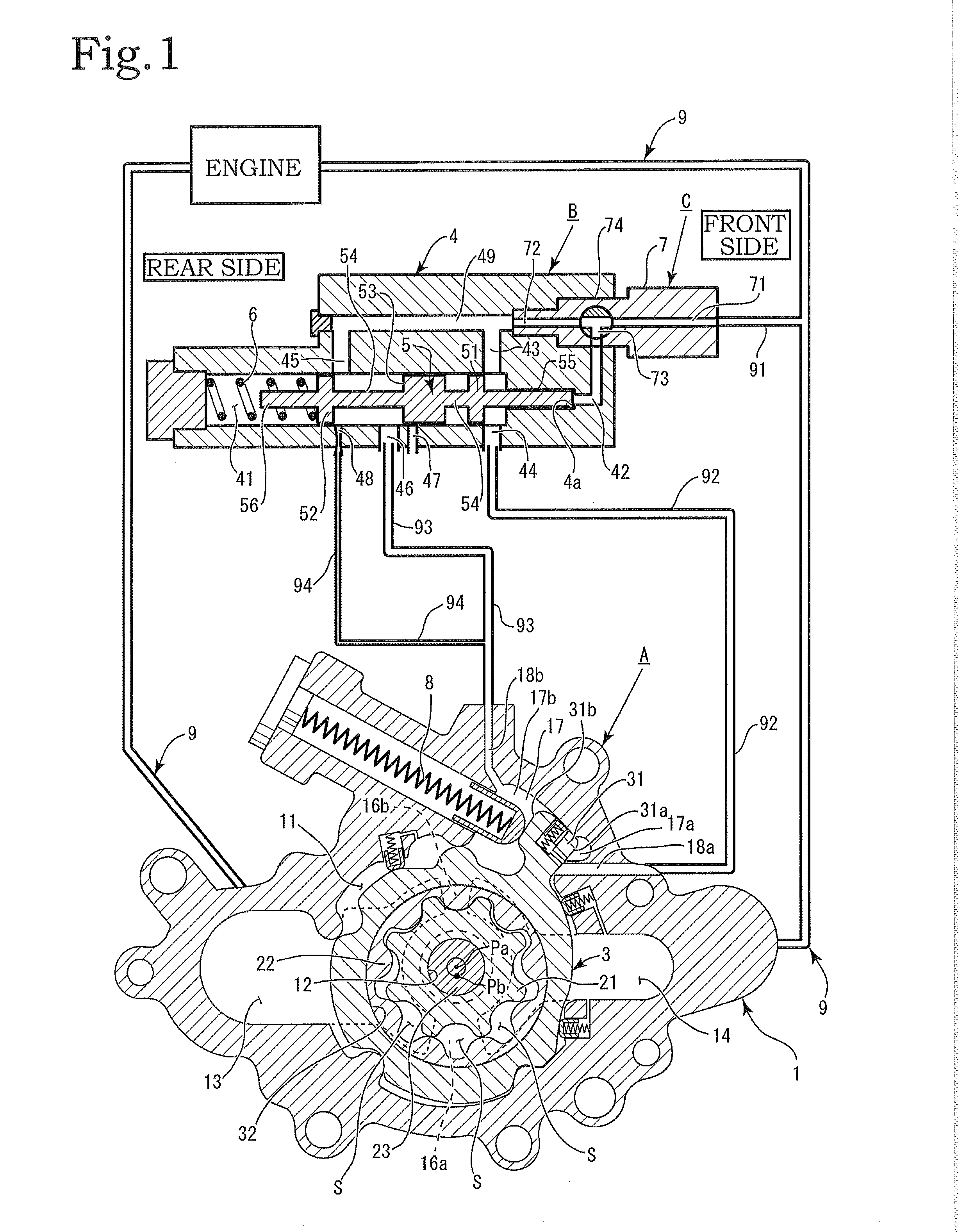
[0024]An embodiment of the present invention is described below on the basis of the drawings. As shown in FIG. 1, the present invention is configured principally by an oil pump A, a hydraulic control valve B and an operating valve C. The oil pump A mainly circulates oil to an automobile engine, and is of a variable-capacity type in which the discharge amount can be varied disproportionately with respect to the engine speed. The operation of varying the discharge amount of the oil pump A is carried out by the hydraulic control valve B and the operating valve C which are provided in an oil circuit 9 that circulates oil from the oil pump A to the engine.

[0025]There exist various structures for the oil pump A, but in the present invention, an internal gear type of pump is described (see FIG. 1). The oil pump A is configured by a pump housing 1, an inner rotor 21, an outer rotor 22 and an outer ring 3. A rotor chamber 11 is formed in the pump housing 1. A shaft hole 12 into which a drive...


PUM


Abstract

An oil pump structure including: an oil pump having a first hydraulic control chamber and a second hydraulic control chamber; a hydraulic control valve having a valve operating oil passage, a first inflow passage, a second inflow passage, a first outflow passage, a second outflow passage and a drain flow passage; and an oil circuit, wherein the hydraulic control valve is connected to a branching flow passage of the oil circuit; a spool valve body of the hydraulic control valve has a front valve section, a rear valve section and an intermediate valve section, which are formed perpendicularly to the axial direction of a connecting shaft; an axial-direction dimension of the intermediate valve section is larger than an axial-direction dimension of the second outflow passage; the second outflow passage and the drain flow passage are both accommodated temporarily between the intermediate valve section and the front valve section due to movement of the spool valve body; and in the hydraulic control valve, a control hydraulic pressure is applied at all times to the first hydraulic control chamber, and the control hydraulic pressure is increased and decreased in the second hydraulic control chamber.

Description

BACKGROUND OF THE INVENTION[0001]1. Field of the Invention[0002]The present invention relates to an oil pump structure for stabilizing discharge pressure of an oil pump of a variable-capacity type, which is used in a vehicle engine, or the like.[0003]2. Description of the Related Art[0004]As oil pumps for automobile engines, there are variable-capacity oil pumps in which the discharge amount can be increased and decreased. Among these, there are pumps wherein the operation of varying the discharge amount is performed by hydraulic means. A specific example of a pump of this kind is disclosed in Japanese Patent Application Publication No. 2012-145095. In Japanese Patent Application Publication No. 2012-145095, as a means for varying the discharge amount, an adjustment ring (14) is moved, thereby causing the pump capacity to increase or decrease. A hydraulic valve is used as means for moving the adjustment ring (14).SUMMARY OF THE INVENTION[0005]In Japanese Patent Application Publicati...

Claims


Application Information

Patent Timeline
IPC IPC(8): F04C14/24F04C2/10F04C14/18
CPCF04C14/24F04C14/18F04C2/10F04C14/226F04C2/102
Inventor MIYAJIMA, JUNICHIWATANABE, TAKATOSHILZUTSU, MASATOOGAWARA, MASAKI
Owner YAMADA SEISAKUSHO KK
Why Eureka
Try Eureka