Aircraft flight characteristic measurement

a flight characteristic and aircraft technology, applied in the field of aircraft flight characteristic measurement, can solve the problems of noise generated from the inability of ground measuring systems to accurately measure sound, and the noise generated by the top of the rotor, so as to minimize the detection of wind noise by the microphone, and avoid background noise

Inactive Publication Date: 2016-03-31
AEROACOUSTIC METHODS LLC
View PDF16 Cites 3 Cited by
  • Summary
  • Abstract
  • Description
  • Claims
  • Application Information

AI Technical Summary

Benefits of technology

[0017]When a microphone or other sound-measuring instrument is suspended by a line from a hot air balloon basket, the balloon can be positioned above a flight path of a rotorcraft. The balloon may ideally be positioned more than three hundred feet above the rotorcraft flight path, allowing measurement of far-field noise. Although the hot air burner is turned off during measurements to avoid background noise, a typical hot air balloon can maintain an altitude with not more than one hundred foot change for about 45 seconds of measuring time, by applying the burner for 10-15 seconds when measurements are not being made. Furthermore, movement of the balloon by the wind actually minimizes detection of wind noise by the microphone.
[0018]The claimed method allows measurement of a wide range of directivity angles of rotorcraft noise. Once the floating platform is positioned, different flight paths can be chosen beneath the platform, at a variety of angles relative to the ground, to enable measurements to be made of sound emitted above the rotors at different angles.
[0019]The floating platform can be piloted to allow for in-flight corrections and modifications of measuring equipment. Alternatively, the floating platform can be unpiloted but remotely controlled. Therefore, there is no need to tether the balloon to the ground, providing a safe flight path for the measured aircraft beneath the balloon or dirigible.

Problems solved by technology

However, ground measuring systems are not useful for accurately measuring sound which is experienced primarily above the aircraft, such as above-the-vehicle acoustic radiation which would be observed if a helicopter was flying in a canyon below the position in which noise was being detected.
Furthermore, rotorcraft frequently maneuver in ways which cause the rotors not to be parallel with the ground, so that the noise generated from the top of the rotors is perceived from areas generally below and beyond the aircraft.
This reflected sound observed by the elevated measuring device is not easily suppressed or distinguished from direct sound, making it difficult to accurately measure just the actual sound generated by the aircraft.
However, because the aircraft-mounted measuring devices are exposed to the wind, sound measurements may reflect the background noise generated by the wind.
In addition, it is risky to fly the aircraft directly above and forward of the vehicle being measured since wake from the measuring aircraft could create unsteady aerodynamic disturbances, making formation flying difficult.
This risk is particularly acute when obtaining measurements of sound emitted directly above a rotorcraft, since wake from the measuring aircraft could create unsteady aerodynamic rotor disturbances.
Furthermore, the wake of the measuring aircraft may change the airflow around the rotor of the rotorcraft, affecting the true sound characteristics for which measurements are sought.
However, because the microphones are mounted directly to the aircraft, the range of radiation angles that can be captured are limited.
It is particularly difficult to measure lower frequency noise generated by the main rotor of a helicopter by such methods.

Method used


Image

  • Aircraft flight characteristic measurement
  • Aircraft flight characteristic measurement
  • Aircraft flight characteristic measurement

Examples


Embodiment Construction

[0025]The present invention concerns a method and device for measuring external characteristics of aircraft. In the following description, numerous specific details are set forth in order to provide a thorough understanding of the present invention. It will be obvious, however, to one skilled in the art that the present invention may be practiced without these specific details. Some well-known methods and structures have not been set forth in order not to unnecessarily obscure the description of the present invention.

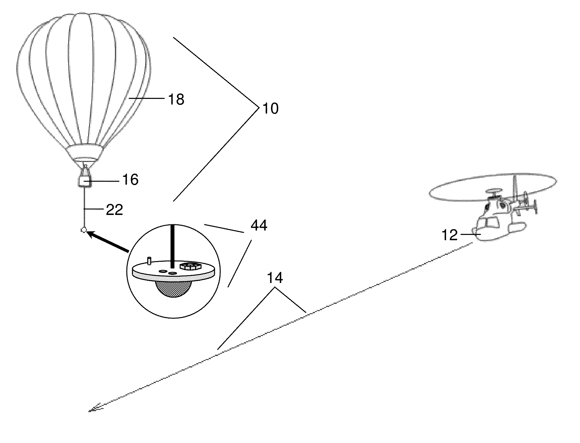
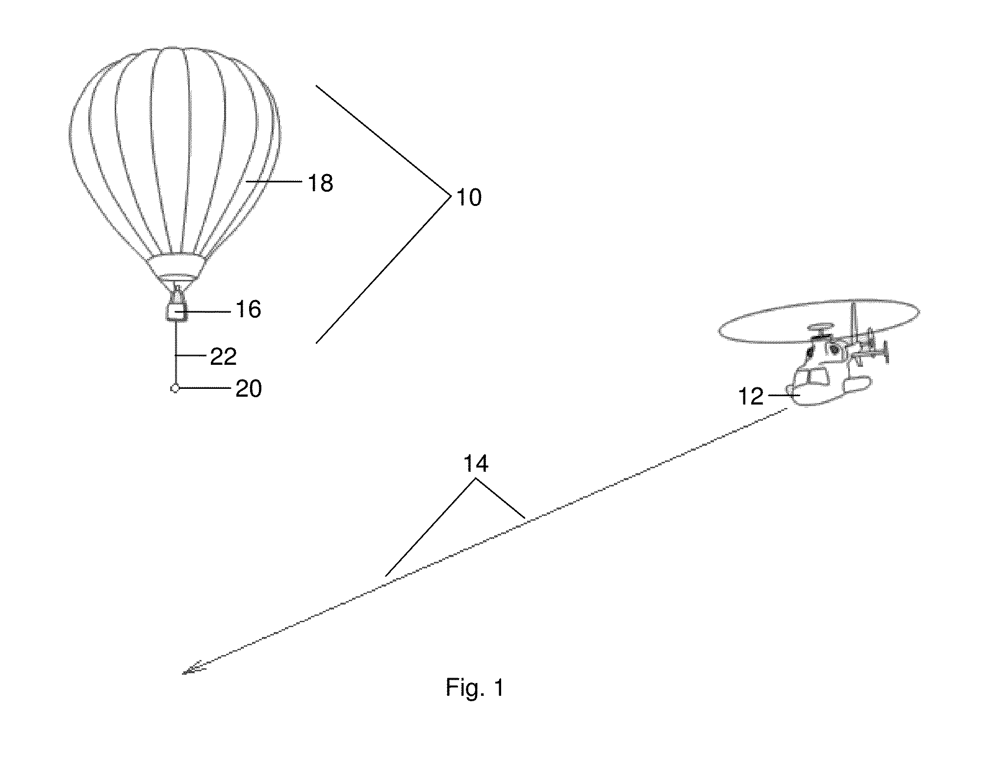
[0026]As best shown in FIG. 1, a system 10 for measuring external characteristics of aircraft 12 relies on a measuring instrument 20 supported by a floating platform 18. The particular measuring instrument 20 is chosen depending on the type of characteristics to be measured. For example, if the system 10 is to be used to measure acoustic characteristics of a particular aircraft 12, a microphone and analog to digital converter may beneficially be selected as the instrume...


PUM


Abstract

A method and device of measuring external flight characteristics of aircraft, including fixed-wing, rotorcraft, and Unmanned Aerial Vehicles, utilizes one or more floating platforms, each supporting one or more measuring instruments. The floating platform may be a hot air balloon, dirigible or other quasi-neutrally-buoyant airship, untethered to avoid interference between the aircraft being measured and any tether. Measurement of rotorcraft acoustic characteristics is particularly enhanced by permitting measurements that account for directionality of noise sources and are not affected by wind or reflected noise.

Description

BACKGROUND OF THE INVENTION[0001]1. Field of the Invention[0002]The present invention relates to a method and device for measuring external flight characteristics of aircraft.[0003]2. Description of the Prior Art[0004]As aircraft improvements are designed and implemented, it is advantageous to accurately measure various external characteristics of each model, to determine relative advantages and consider needed improvements. For example, since it is desirable to minimize sound generated by helicopters in a combat situation, it is important to be able to accurately measure actual noise resulting from each type of helicopter.[0005]A number of aircraft characteristic measurement methods are currently used. Ground-to-vehicle microphone noise measurements of fixed- and rotary-wing aircraft are typically accomplished through arrays of microphones affixed to stationery ground-boards set on the surface of the ground. Such arrays permit a fairly simple method of measuring sound generated by ...

Claims


Application Information

Patent Timeline
Patent Type & Authority Applications(United States)
IPC IPC(8): G01H17/00G01M17/00
CPCG01M17/00G01H17/00G01H3/00
Inventor SCHMITZ, FREDRIC, H.KOUSHIK, N., SUDARSHANASICKENBERGER, RICHARD, D.ECKERT, WILLIAM, T.
Owner AEROACOUSTIC METHODS LLC
Why Eureka
Try Eureka