Adjustable orthodontic bracket and method

a technology of orthodontic brackets and brackets, which is applied in the field of adjustable orthodontic brackets and methods, can solve the problems of excessive crowding of teeth, difficulty if not impossible to precisely position each bracket, and increased difficulty in precise positioning of brackets

Inactive Publication Date: 2016-04-07
IZADI MOHAMMAD
View PDF17 Cites 3 Cited by
  • Summary
  • Abstract
  • Description
  • Claims
  • Application Information

AI Technical Summary

Benefits of technology

[0010]Briefly, an adjustable orthodontic bracket in accordance with the present invention includes a metal base member adapted to be rigidly secured directly to a tooth by a very thin layer of an orthodontic adhesive. Further, a relatively thin layer of lead free heat softenable material for joining two metal surfaces rigidly together is provided together with an orthodontic bracket having a base to fit within a surface area of the base member and an engagement receiver for an archwire by which forces are developed in a patient's mouth. In the device in accordance with the invention, the base member overlaps the base of the bracket surrounding the base so that the bracket can be adjusted in all directions around the base member without overlapping the periphery of the base member.

Problems solved by technology

When orthodontic brackets (braces) are bonded to the patient's teeth at an initial treatment, it is very difficult if not impossible to precisely position each bracket.
The problem is exacerbated by a number of issues.
For example, excess crowding of the teeth, angulations of the teeth, lack of access and at times human error or inability to precisely position a bracket on a specific tooth.
A further problem confronting the orthodontist is that the realignment of the teeth following the initial treatment, it becomes apparent that some of the brackets that have been bonded to a patient's teeth need to be repositioned.
This requires removal of the originally bonded bracket from the tooth enamel that causes pain and discomfort, frequently damages the bracket, requires a new bracket, requires removal of the existing bonding material on the patient's teeth, repairing the tooth surface and rebonding a new bracket in the ideal position.
This procedure is costly, time consuming and may not necessarily be the last time the orthodontist is replacing that bracket.

Method used


Image

  • Adjustable orthodontic bracket and method
  • Adjustable orthodontic bracket and method
  • Adjustable orthodontic bracket and method

Examples


Embodiment Construction

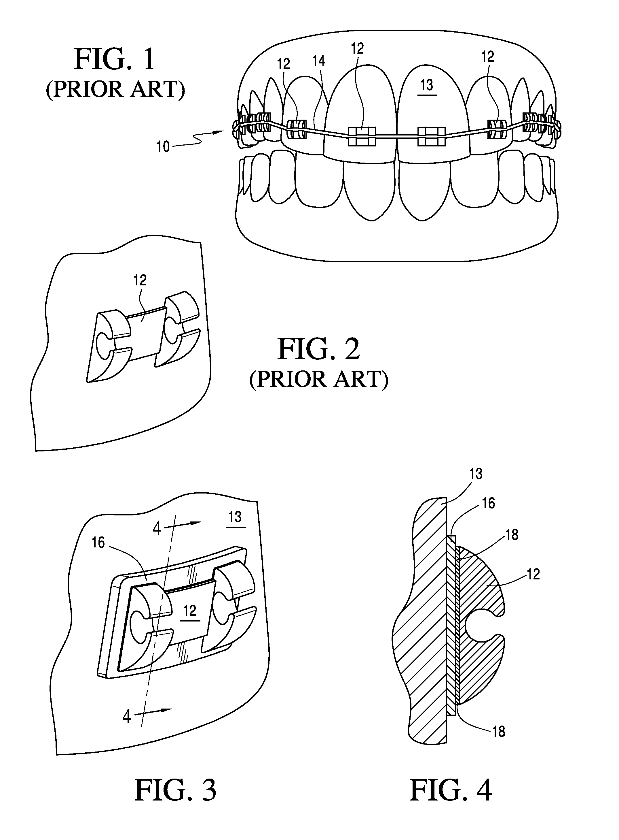
[0032]As illustrated, in FIG. 1 a set of orthodontic braces 10 includes a plurality of orthodontic brackets 12 and an archwire 14 for applying forces to reposition the upper teeth in a patient's mouth. As shown in FIG. 1, the orthodontic brackets 12 are directly bonded to the surfaces of a patient's upper teeth. The latter feature is more clearly shown in FIG. 2 wherein a single bracket 12 is securely bonded to a single tooth by an orthodontic adhesive. A bonding material commonly used in orthodontics to adhere a bracket to a tooth surface are composite resins such as Transbond XT (Ref 712-036 manufactured by 3M Unitek), or other similar products manufactured by Ormco, Densply or Reliance, or thermoplastic material.

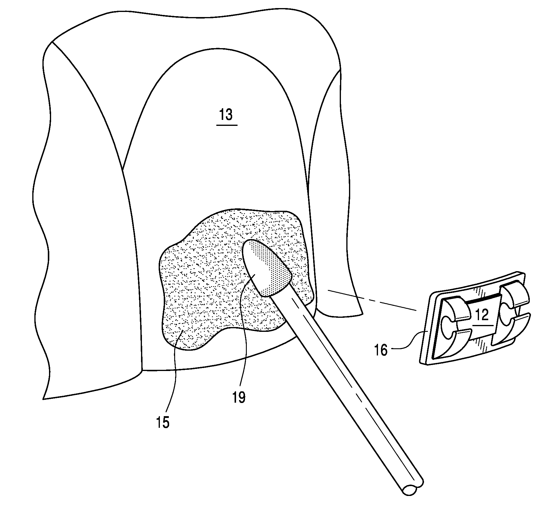
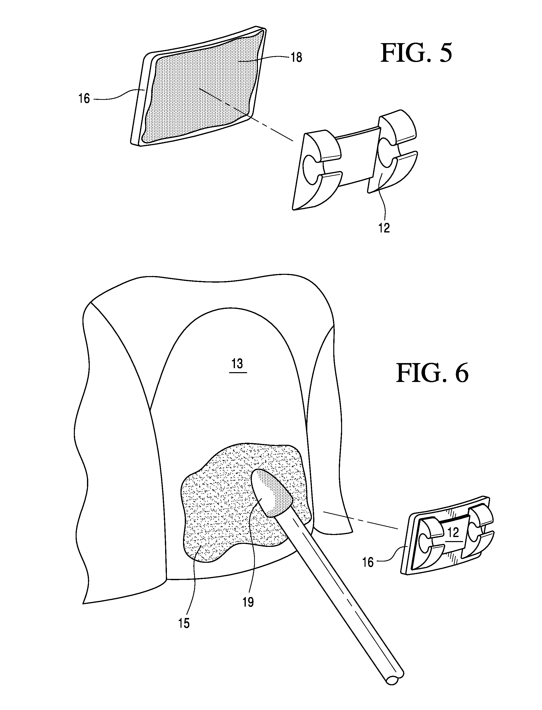
[0033]For contrast, FIG. 3 illustrates a base member 16 preferably of metal that is bonded directly to a tooth by a thin layer of an orthodontic adhesive and is positioned between a relatively flat base of the orthodontic bracket 12 and the tooth 13. It should be recogniz...


PUM


Abstract

A metal base member and a thin layer of an orthodontic adhesive is used to rigidly secure said base member directly to a tooth; a layer of lead-free heat softenable material for joining two metal surfaces rigidly together and an orthodontic bracket having a face to fit within a surface area of the base member and an engagement receiver for an archwire by which forces are developed in a patient's mouth. In addition, the base member overlaps the base of the bracket by up to about 1.0 mm surrounding the base so that the bracket can be adjusted by an amount of up to about 1.0 mm in all directions around the base member without overlapping the periphery of the base member.

Description

FIELD OF THE INVENTION[0001]This invention relates to an adjustable orthodontic bracket and a method for adjusting an orthodontic bracket without breaking a bond between a patient's tooth and the bracket.BACKGROUND FOR THE INVENTION[0002]The practice of orthodontics requires a considerable amount of chair time with patients so that perfect or near perfect alignment of the patient's teeth can be achieved. When orthodontic brackets (braces) are bonded to the patient's teeth at an initial treatment, it is very difficult if not impossible to precisely position each bracket. The problem is exacerbated by a number of issues. For example, excess crowding of the teeth, angulations of the teeth, lack of access and at times human error or inability to precisely position a bracket on a specific tooth.[0003]A further problem confronting the orthodontist is that the realignment of the teeth following the initial treatment, it becomes apparent that some of the brackets that have been bonded to a ...

Claims


Application Information

Patent Timeline
Patent Type & Authority Applications(United States)
IPC IPC(8): A61C7/14A61C7/20A61C1/00A61C7/16
CPCA61C7/146A61C1/0046A61C7/20A61C7/16
Inventor IZADI, MOHAMMAD
Owner IZADI MOHAMMAD
Why Eureka
Try Eureka