

Micro electrochemical energy storage cells
a technology of energy storage cells and micro-electrochemicals, which is applied in the manufacture of secondary cells, solid-state devices, and final products. it can solve the problems of low energy and power of batteries, and achieve the effect of increasing capacity and superior performan
- Summary
- Abstract
- Description
- Claims
- Application Information
AI Technical Summary
Benefits of technology
Problems solved by technology
Method used
Image

Examples
example 1
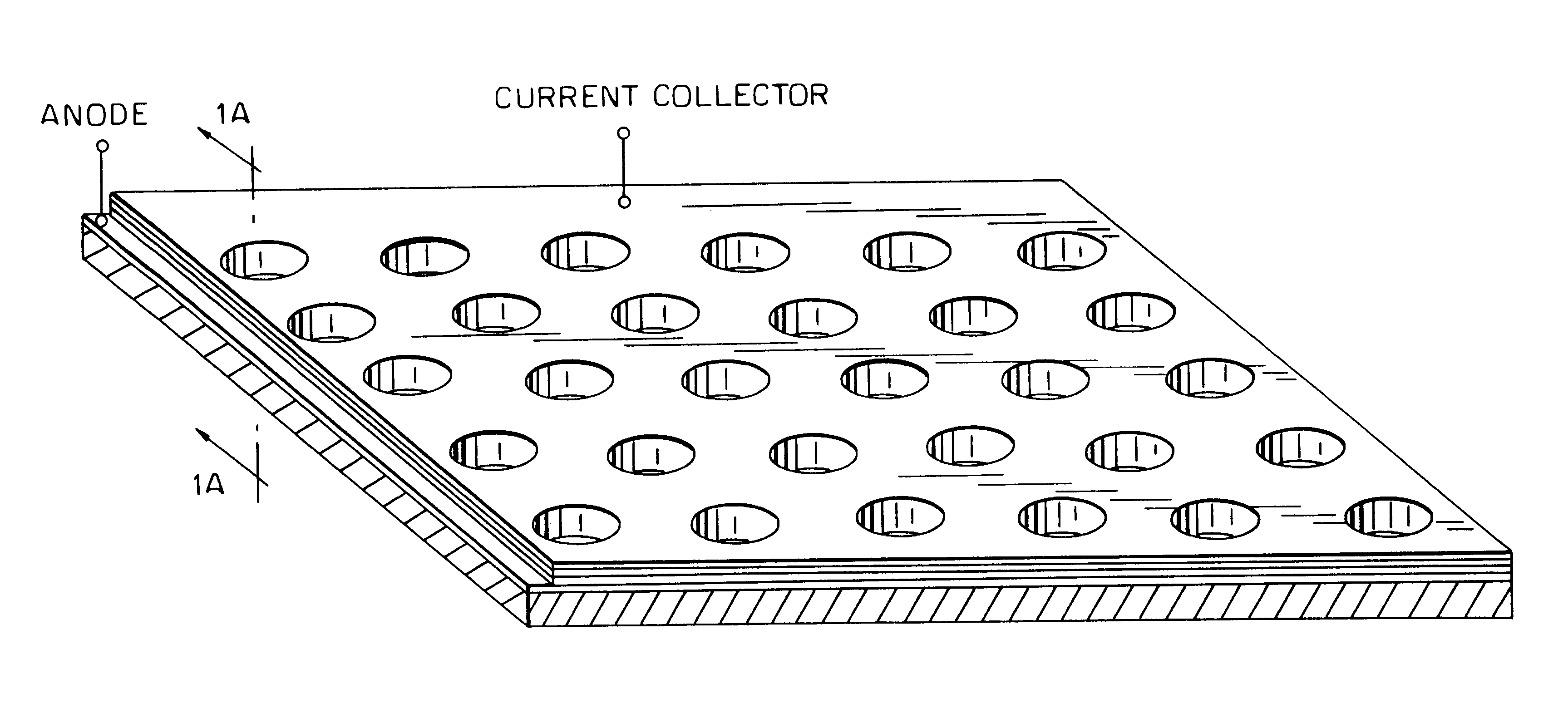
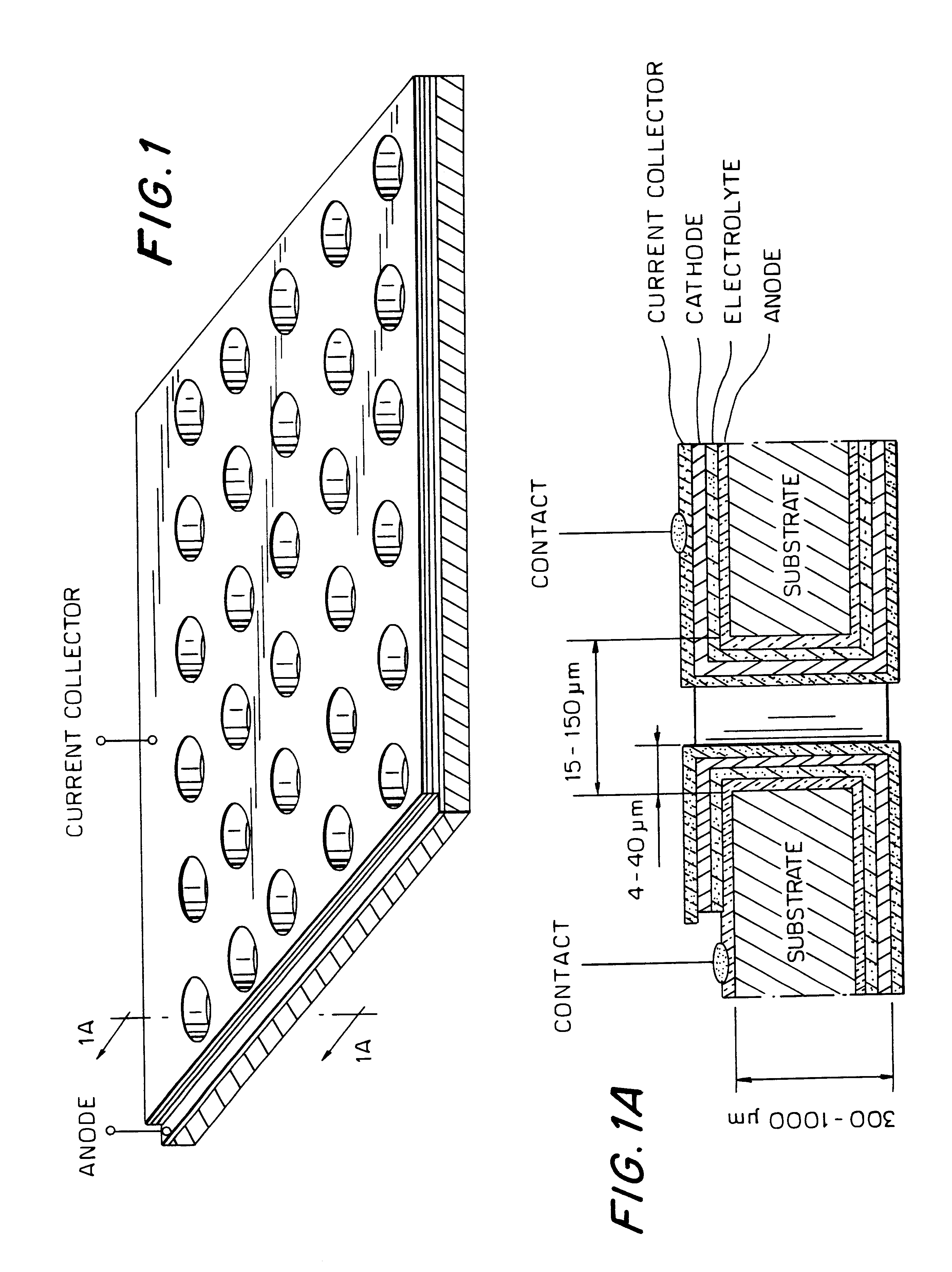
A microbattery, consisting of a carbon anode, composite polymer electrolyte and composite LiCoO.sub.2 cathode was fabricated in the discharged state on a perforated 400 micron thick silicon wafer which contains 100 micron in diameter through holes. A thin carbon film was deposited by CVD at 850 Celsius by passing a C.sub.2 H.sub.4 (10%) Ar (90%) gas mixture for four minutes over the wafer.
A second layer of a composite polymer electrolyte (CPE) was deposited (inside an Ar filled glove box) over the carbon layer by a short vacuum dipping at 50-65 Celsius in acetonitrile (30 ml) suspension consisting of 0.6 g PEO (5.times.10.sup.6 MW), 0.05 g EC, 0.1 g LiN(CF.sub.3 SO.sub.2).sub.2 (imide) and 0.03 g alumina. After drying, a second layer of CPE was deposited in the same way to get the desired CPE thickness. A thin cathode layer was deposited (inside the glove box) over the CPE layer by a short vacuum dipping in cyclopentanone (10 ml) suspension consisting of 2 g of ball milled LiCoO.sub...
example 2
A DLC, consisting of two carbon electrodes, and composite polymer electrolyte was fabricated on a perforated 400 micron thick silicon wafer which contains 100 micron in diameter through holes in a similar way as described in Example 1. A thin high surface area carbon powder (500 m.sup.2 / g) (made by 1000 Celsius pyrolysis of cotton) layer was deposited (inside the glove box) on the perforated wafer by a short vacuum dipping in cyclopentanone (10 ml) suspension consisting of 1 g of ball milled carbon, 0.05 g carbon black and 0.1 g PVDF copolymer (ELF 2800). A second layer of a composite polymer electrolyte (CPE) was deposited (inside Ar filled glove box) over the carbon layer by a short vacuum dipping at 50-65 Celsius in an acetonitrile (30 ml) suspension consisting of 0.6 g PEO (5.times.10.sup.6 MW), 0.05 g EC, 0.1 g LiN(CF.sub.3 SO.sub.2).sub.2 (imide) and 0.03 g alumina. After drying, another layer of CPE was deposited in the same way to get the desired CPE thickness. A third high...
example 3
A microbattery, consisting of four thin films: a carbon anode, Al doped Li.sub.2 CO.sub.3 solid electrolyte, LiCoO.sub.2 cathode and carbon current collector was fabricated in the discharged state on a perforated 400 micron thick silicon wafer which contains 60 micron in diameter through holes. A thin carbon film was CVD deposited at 850 Celsius by passing a C.sub.2 H.sub.4 (10%) Ar (90%) gas mixture for three minutes over the wafer. A second layer of thin Al doped Li.sub.2 CO.sub.3 solid electrolyte was deposited at 475 Celsius on the first one by CVD following the procedure described in P. Fragnaul et al. J. Power Sources 54, 362 1995. A third thin layer of LiCoO.sub.2 cathode was deposited at 500 Celsius on the second one following the procedure described in P. Fragnaul et al. J. Power Sources 54, 362 1995. A fourth thin carbon current collector layer was deposited at 800 Celsius on the third one in the same way as the first one.
This cell was cycled (as described in example 1) at...
PUM
| Property | Measurement | Unit |
|---|---|---|
| Fraction | aaaaa | aaaaa |
| Diameter | aaaaa | aaaaa |
| Electrical conductor | aaaaa | aaaaa |
Abstract
Description
Claims
Application Information