Method and apparatus for evaluating the resistivity of formations with high dip angles or high-contrast thin layers

a resistivity and thickness technology, applied in the field of well logging, can solve the problems of corrupting measurement, affecting quantitative formation evaluation, and practical limitations of conventional propagation and induction techniques for evaluating formation resistivity

Inactive Publication Date: 2001-10-16
SCHLUMBERGER TECH CORP
View PDF18 Cites 176 Cited by
  • Summary
  • Abstract
  • Description
  • Claims
  • Application Information

AI Technical Summary

Benefits of technology

In a second aspect of the invention, another coil configuration is utilized to provide a mutual balance condition to determine the formation conductivity.

Problems solved by technology

Conventional propagation and induction techniques for evaluating the resistivity of formations have practical limitations.
Neighboring layers in high-contrast (in terms of resistivity) thin-layer formations can corrupt the measurement results--known as shoulder effect.
The TM horns observed are useful to detect layer boundaries, but are detrimental for quantitative formation evaluation.
This method requires time-consuming model calculations, and cannot be applied at the well site while logging.
The techniques proposed by these disclosures do not address the evaluation of high-contrast thin-layer formations at high dip angles.

Method used


Image

  • Method and apparatus for evaluating the resistivity of formations with high dip angles or high-contrast thin layers
  • Method and apparatus for evaluating the resistivity of formations with high dip angles or high-contrast thin layers
  • Method and apparatus for evaluating the resistivity of formations with high dip angles or high-contrast thin layers

Examples


Embodiment Construction

In the interest of clarity, not all features of actual implementation are described in this specification. It will be appreciated that although the development of any such actual implementation might be complex and time-consuming, it would nevertheless be a routine undertaking for those of ordinary skill in the art having the benefit of this disclosure.

4.1 Overview of the Problem

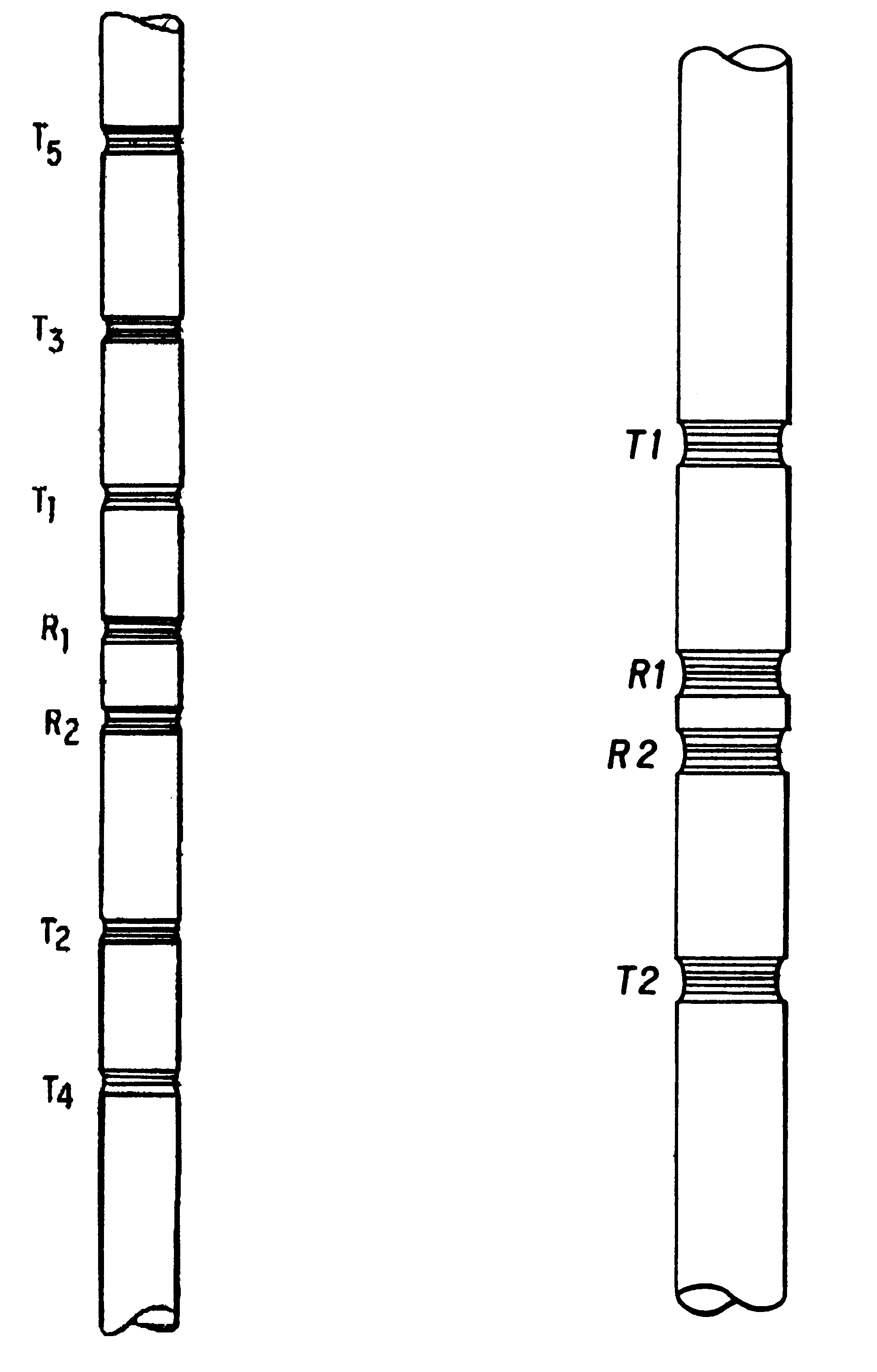
FIG. 1 shows the coil layouts of two logging tool designs A, B, disclosed in the '940 and '343 patents, which can be used to implement the present invention. Each tool includes at least two transmitters Tn (n>0) and at least one pair of receivers Rn (n>0). As discussed above, energy emitted into a formation by a transmitter Tn propagates in the formation and is detected by a receiver Rn as a complex-valued "phasor" voltage (not shown). Denoting the voltages detected at the receivers R1, R2 as V.sub.1, V.sub.2 (not shown), the processing of these measurements is based on the relative phase delay and attenuati...


PUM


Abstract

A method and apparatus for evaluating the resistivity of earth formations surrounding a borehole, particularly high-contrast thin-layer formations or at high dip angles. The method involves positioning a pair of transmitters and a pair of receivers within the borehole, the receivers or transmitters adhering to specific spacing limitations, alternately transmitting electromagnetic energy of a particular frequency and receiving voltage data associated with the transmitted energy. Multiple voltage data are acquired and a representation of a resistivity or conductivity profile is created from a formulated difference of the data from a particular depth and/or neighboring depths. The apparatus forms part of a well logging system including a well tool adapted to be moveable through a borehole. The apparatus being coupled to the well tool and adapted with means to input voltage data developed by the receivers disposed on the well tool. The apparatus further adapted with means for performing calculations to determine a conductivity profile and for recording the profile on an output record medium.

Description

1. BACKGROUND OF THE INVENTION1.1 Field of the InventionThis invention relates to the field of well logging and, more particularly, to a well logging method and apparatus for evaluating formation properties, such as resistivity, in high-contrast thin-layer formations or at high dip angles, with greater accuracy than prior techniques. Still more particularly, this invention relates to an improved technique for acquiring multiple data during resistivity logging, processing these data, and creating a representation of resistivity or conductivity from a formulated difference of data from a particular depth and / or neighboring depths.1.2 Description of Related ArtResistivity logging is a well-known form of electromagnetic ("EM") propagation logging. [In the present application, any references to resistivity are intended to encompass its inverse, conductivity, and vice-versa.] Resistivity logging is used for locating and evaluating the properties of potential hydrocarbon bearing zones in s...

Claims


Application Information

Patent Timeline
Patent Type & Authority Patents(United States)
IPC IPC(8): G01V3/28G01V3/18
CPCG01V3/28
Inventor MINERBO, GERALD N.ROSTHAL, RICHARD A.
Owner SCHLUMBERGER TECH CORP
Why Eureka
Try Eureka