[0007] In another aspect of the invention, the anchoring element comprises a
helix configuration formed from cannula or a flat sheet of material. The
helix wraps around the strut of the
prosthesis and spaces between the windings provide convenient points for
laser weld to
affix the anchoring element, thus limiting the extent of weld annealing around the basal region of the barb.
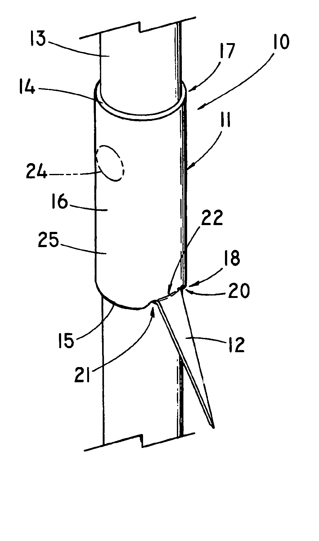
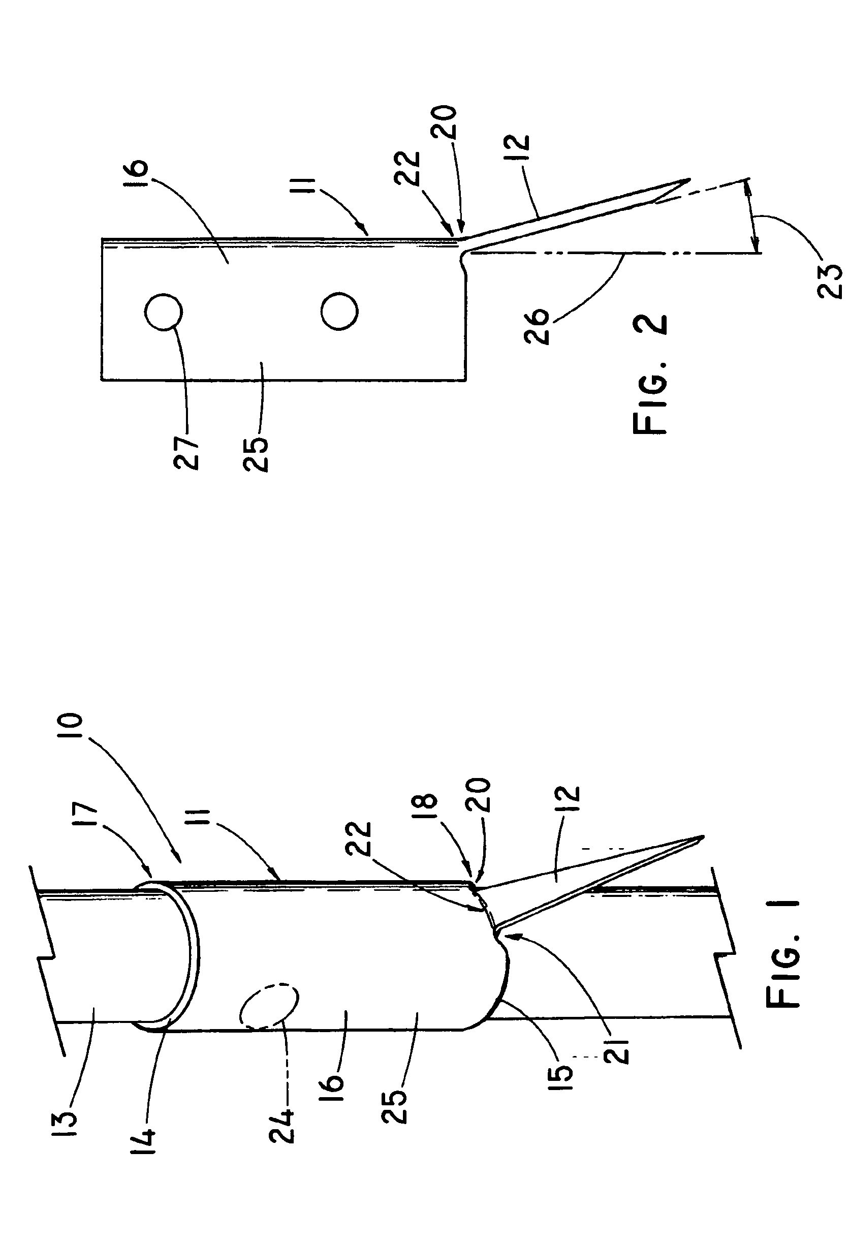
[0008] In still another aspect of the invention, the anchoring element is slidably disposed on the strut rather than being permanently affixed. The cannula, or anchoring element formed from flat stock is inserted over or around the strut. Stops that are either attached to, incorporated into the strut, or occur as part of the frame design, limit the longitudinal movement of the anchoring element. By allowing the anchoring element comprising the barb to move in response to forces concentrated at a particular
anchor point, it will be less likely to cause the barb to fracture and perhaps lead to migration of the prosthesis. Additionally, a slidable barb can be advantageously configured as a deployable barb
system where the barb assumes a first configuration not adapted to engage tissue, such as for the delivery or initial placement of the prosthesis, but is then manipulated into a second configuration or orientation to penetrate the adjacent tissue, such as the luminal wall, and anchor the prosthesis. In a first exemplary embodiment of the present invention, the slidable anchoring element which includes a barb generally extending parallel with the strut, is attached to a actuating
system, such as a tether, which urges the anchoring element over the strut until it contacts a deflecting element, such as a ramped structure, located on the strut which forces the barb outward into a position that is better able to penetrate tissue. Optionally, the anchoring element is configured to engage structure located on the strut that locks the anchoring element into the second, engageable position. In a second embodiment, the prosthesis can be deployed with the barb oriented away from the
tissue surface, whereby the anchoring element and barb are rotated or otherwise urged or moved into position after the prosthesis is deployed at the
implantation site such that the barb tip is able to embed into the adjacent tissue and further anchor the device. Actuation of the anchoring element can be done with releasable tethers, sleeves, sheaths or other mechanisms that restrain the barbs in an inward or otherwise non-engaging orientation, whereby the restraint is released to allow the anchoring element and barbs to resiliently rotate or slide to assume a tissue-engaging position. Spiral threads or grooves, or a twisted strut (e.g., preferable with a non-rounded strut profile) can be used to guide the anchoring element from the first non-engaging position to the second, engageable position. Tethers, wires, pushers, or other mechanical structure may be used to urge the anchoring elements and barbs from a non-engaging position (e.g., via rotation or longitudinal movement of the anchoring element) to one that allows the barbs to penetrate and anchor the device once the prosthesis is in position for final deployment.
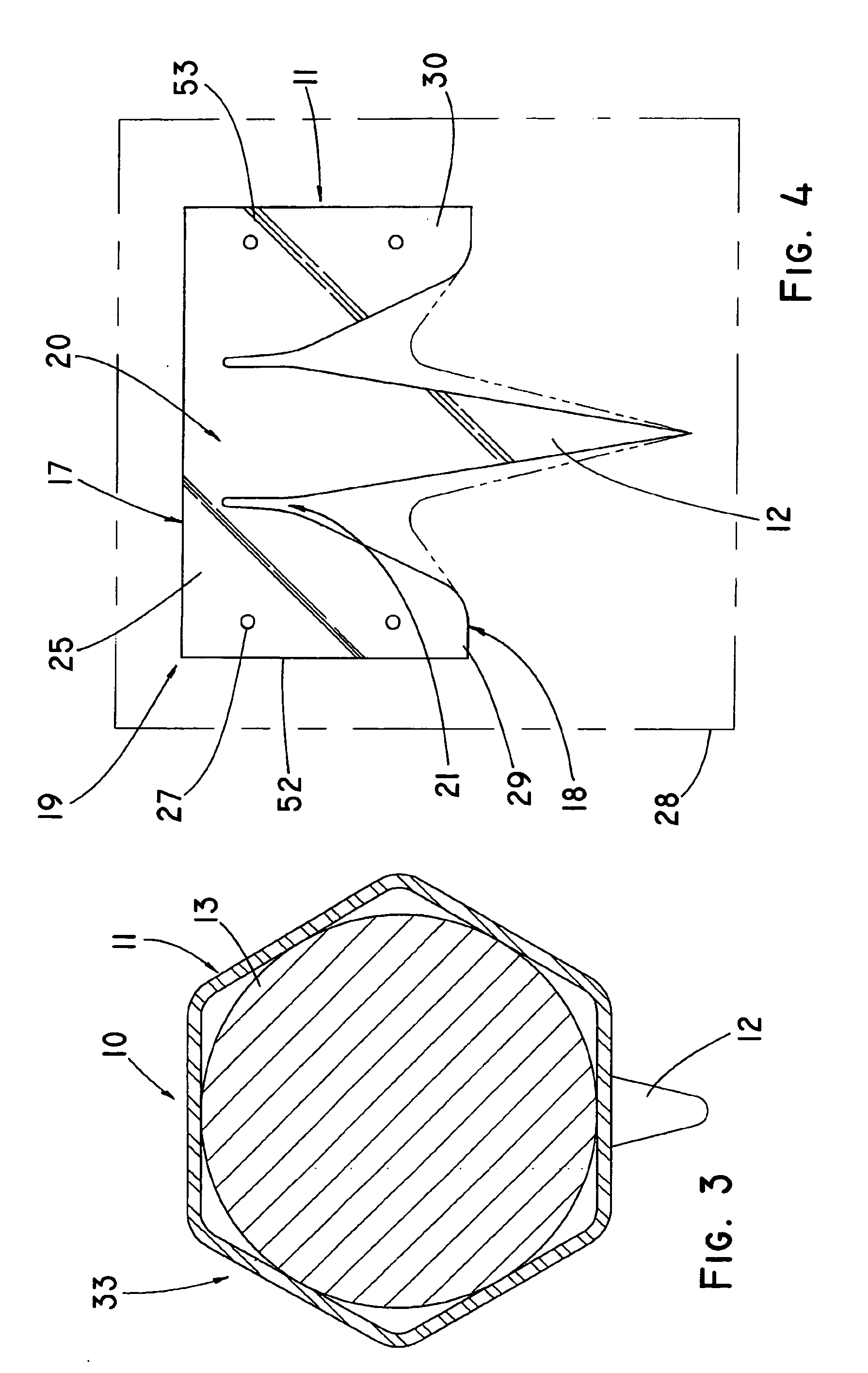
[0009] Optionally, the anchoring element and strut can be configured such that they slidably engage one another in a manner that limits
axial rotation of the anchoring element, thereby ensuring that the barb remains in the desired plane for optimum functionality. This can be accomplished by a variety of methods, including conforming the anchoring element over an at least partially squared strut or having the anchoring element and strut engage one another, such as fitting a tab within a longitudinal groove or other structure, which limits the ability of the anchoring element to twist on the strut while still allowing it to slide longitudinally.

