Antenna for plasma generation and plasma processing device having the same

a plasma generation and processing device technology, applied in the direction of electrical equipment, light sources, electric discharge tubes, etc., can solve the problems of difficult high frequency current flow, insufficient inductive coupling state, and low plasma uniformity, so as to achieve high plasma generation efficiency, suppress the potential difference between two ends of the planar antenna, and high plasma generation efficiency

Active Publication Date: 2016-04-07
NISSIN ELECTRIC CO LTD
View PDF22 Cites 11 Cited by
  • Summary
  • Abstract
  • Description
  • Claims
  • Application Information

AI Technical Summary

Benefits of technology

[0014]According to the technique disclosed in Patent Literature 3, because it is an internal antenna, the plasma generation efficiency is high compared to the case of an external antenna, and the condenser is respectively disposed in one or more grooves formed on the main surface of the planar antenna on the inner side of the vacuum chamber. Thus, it has the feature that the potential difference between two ends of the planar antenna can be suppressed even if the planar antenna is lengthened to cope with the size increase of the substrate. However, the planar antenna may easily hold a two-dimensional direction potential distribution in the plane and causes a corresponding plasma distribution to be easily transferred to the film on the substrate surface. From the aspect of improving this problem, a pipe-shaped antenna conductor is preferred. In the case of a pipe-shaped antenna conductor, however, the technique of disposing the condenser in the groove of the planar antenna as disclosed in Patent Literature 3 is not applicable. A new design around the condenser is therefore required.
[0015]Because the technique disclosed in Patent Literature 3 is an internal antenna, the plasma generation efficiency is high compared to the case of an external antenna, and the condenser is respectively disposed in one or more grooves formed on the main surface of the planar antenna on the inner side of the vacuum chamber. Thus, it has the feature that the potential difference between two ends of the planar antenna can be suppressed even if the planar antenna is lengthened to cope with the size increase of the substrate. However, the planar antenna may easily hold a two-dimensional direction potential distribution in the plane and causes a corresponding plasma distribution to be easily transferred to the film on the substrate surface, compared to a pipe-shaped antenna.
[0016]Therefore, the invention provides an antenna that is disposed in a vacuum chamber for generating an inductively coupled plasma. The antenna uses a metal pipe in the antenna conductor and can suppress increase of the impedance of the antenna even if the antenna is lengthened. The invention further provides a plasma processing device that generates an inductively coupled plasma in a vacuum chamber by applying a high frequency current to the antenna disposed in the vacuum chamber. The plasma processing device uses a metal pipe in the antenna conductor and can suppress increase of the impedance of the antenna even if the antenna is lengthened.

Problems solved by technology

As a result, the potential difference that occurs between two ends of each linear conductor close to the dielectric window increases and causes the plasma uniformity to drop.
In addition, due to the increase of the impedance of each linear conductor, it becomes difficult for the high frequency current to flow and the inductive coupling state may not be achieved efficiently.
Moreover, because it is an external antenna and the inductive coupling proceeds through the dielectric window, the distance to the plasma space is long due to the thickness of the dielectric window material and the plasma generation efficiency is low compared to the case of an internal antenna.
As a result, the potential difference that occurs between two ends of each antenna increases and causes the plasma uniformity to drop.
In addition, due to the increase of the impedance of each antenna, it becomes difficult for the high frequency current to flow and the inductive coupling state may not be achieved efficiently.

Method used


Image

  • Antenna for plasma generation and plasma processing device having the same
  • Antenna for plasma generation and plasma processing device having the same
  • Antenna for plasma generation and plasma processing device having the same

Examples


Embodiment Construction

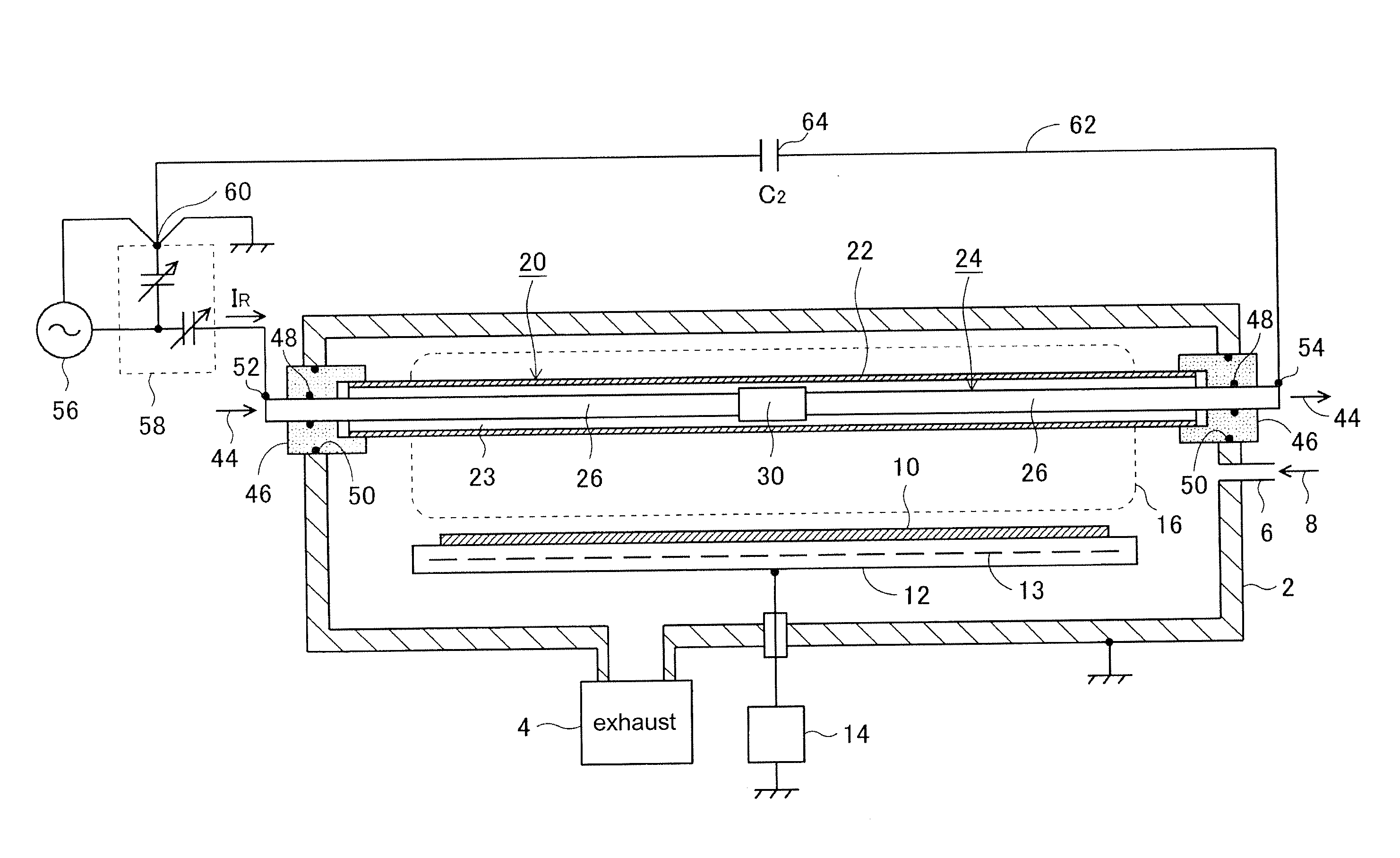
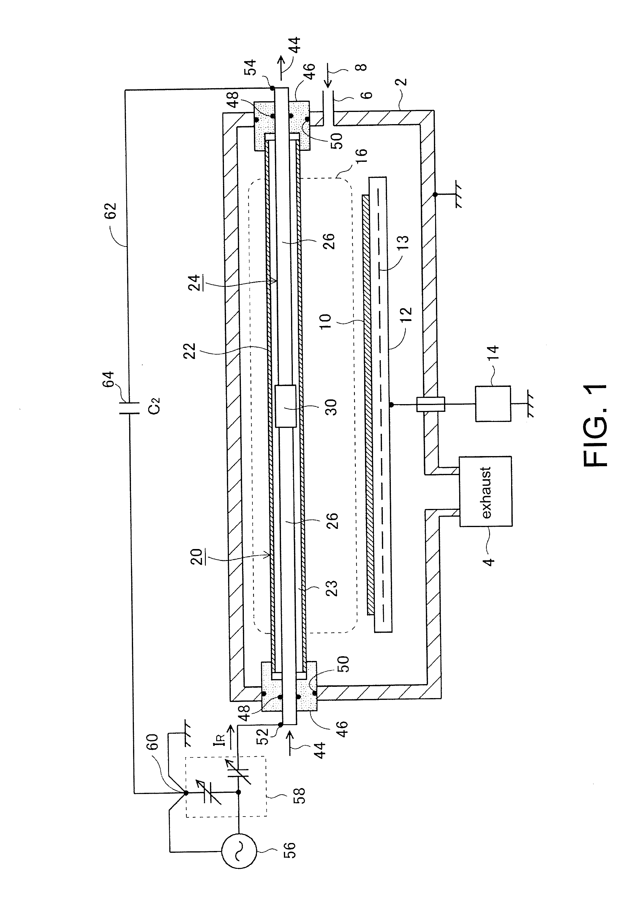
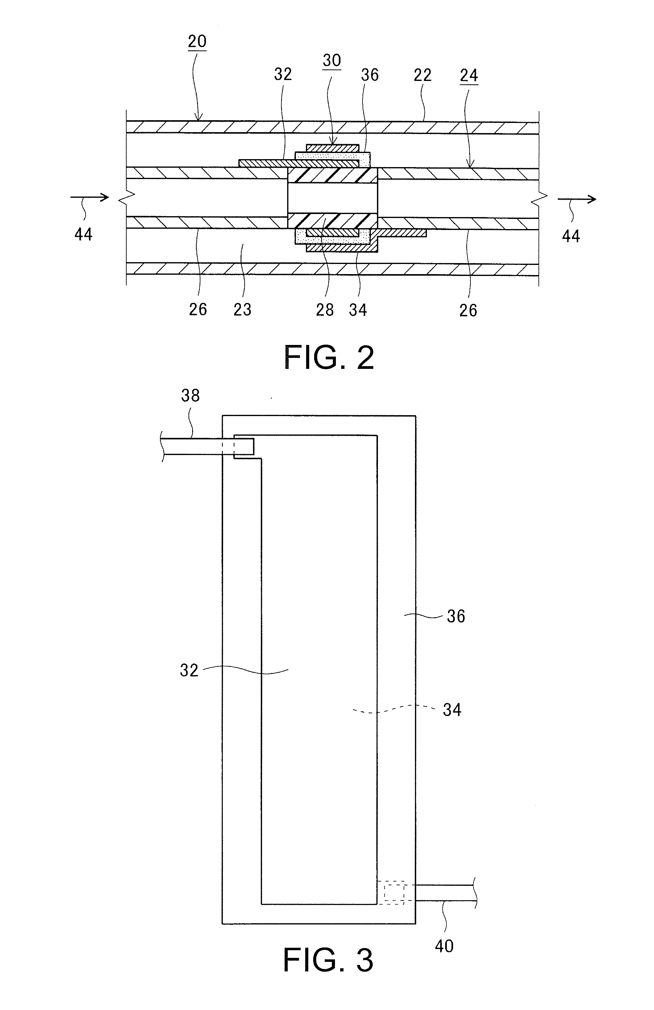
[0043](1) FIG. 1, an embodiment of the antenna, etc., illustrates an example of the plasma processing device that includes the antenna of an embodiment of the invention. FIG. 2 is an enlarged view showing an example of the area around a condenser of the antenna of FIG. 1.

[0044]The plasma processing device includes a vacuum chamber 2, which is evacuated and into which a gas 8 is introduced; an antenna 20, which is disposed in the vacuum chamber 2 and to which a high frequency current IR is applied to generate an inductively coupled plasma 16 in the vacuum chamber 2; and a high frequency power source 56, which applies the high frequency current IR to the antenna 20. The plasma processing device is configured to process a substrate 10 by using the generated plasma 16.

[0045]The substrate 10 is a substrate for flat panel displays (FPD) such as liquid crystal displays and organic EL displays, or a flexible substrate for flexible displays, for example, but not limited to the foregoing.

[004...


PUM


Abstract

Provided are an antenna, which is disposed in a vacuum chamber for generating an inductively coupled plasma, and a plasma processing device. The antenna and the plasma processing device suppress increase of the impedance even if the antenna is lengthened. An antenna 20 is disposed in a vacuum chamber 2 for generating an inductively coupled plasma 16 in the vacuum chamber 2 by applying a high frequency current. The antenna 20 includes an insulating pipe 22 and a hollow antenna body 24 which is disposed in the insulating pipe 22 and in which cooling water flows. The antenna body 24 has a structure that a plurality of metal pipes 26 are connected in series with a hollow insulator 28 interposed between the adjacent metal pipes 26, and each connecting portion has a sealing function with respect to vacuum and the cooling water.

Description

CROSS REFERENCE TO RELATED APPLICATIONS[0001]This application claims the priority benefit of Japan applications serial no. 2014-202880, filed on Oct. 1, 2014, Japan applications serial no. 2015-113934, filed on Jun. 4, 2015, and Japan applications serial no. 2015-084769, filed on Apr. 17, 2015. The entirety of each of the above-mentioned patent applications is hereby incorporated by reference herein and made a part of this specification.BACKGROUND OF THE INVENTION[0002]1. Field of the Invention[0003]The invention relates to an antenna to be applied with a high frequency current for generating an inductively coupled plasma in a vacuum chamber, and a plasma processing device that generates an induced electric field in the vacuum chamber by applying a high frequency current to the antenna disposed in the vacuum chamber to generate an inductively coupled plasma and process a substrate with the plasma. In this application, ions refer to positive ions. The processing applied on the substr...

Claims


Application Information

Patent Timeline
Patent Type & Authority Applications(United States)
IPC IPC(8): H01J37/32H01Q1/36H01Q1/02
CPCH01J37/3211H01Q1/36H01Q1/02H01J37/32522
Inventor ANDO, YASUNORILI, DONGWEI
Owner NISSIN ELECTRIC CO LTD
Why Eureka
Try Eureka