Wire Harness
a wire harness and wire technology, applied in the direction of insulated conductors, cables, electric/fluid circuits, etc., can solve the problems of damage to the conductive path, puncture etc., and achieve the effect of reducing the flexing of the exterior member, and increasing the rigidity of the straight tubular portion
- Summary
- Abstract
- Description
- Claims
- Application Information
AI Technical Summary
Benefits of technology
Problems solved by technology
Method used
Image

Examples
embodiment 1
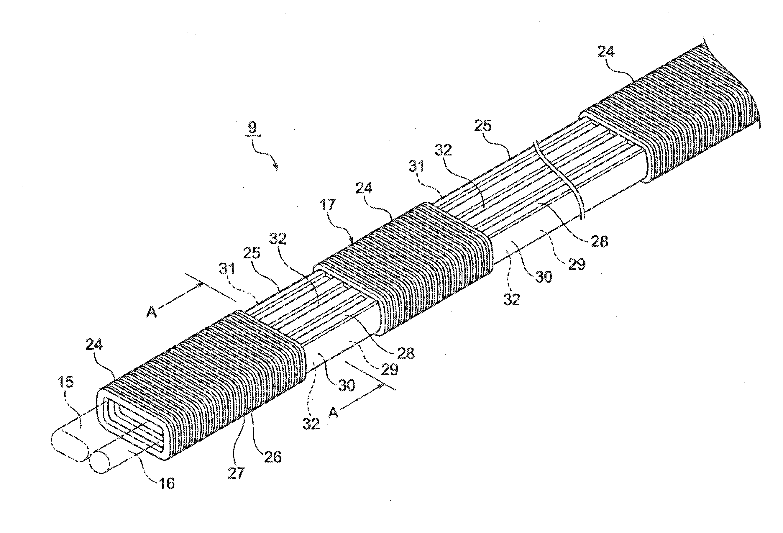
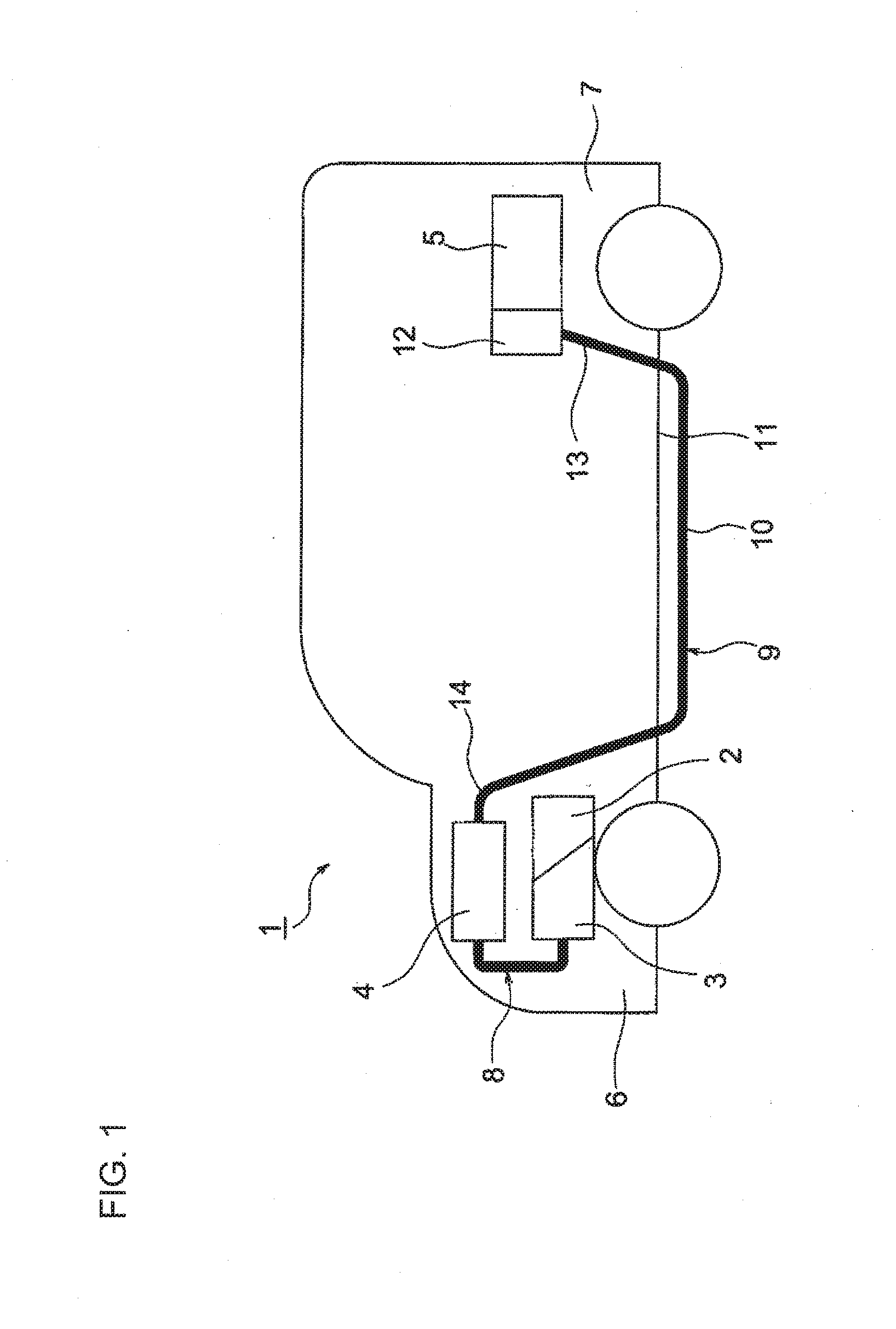
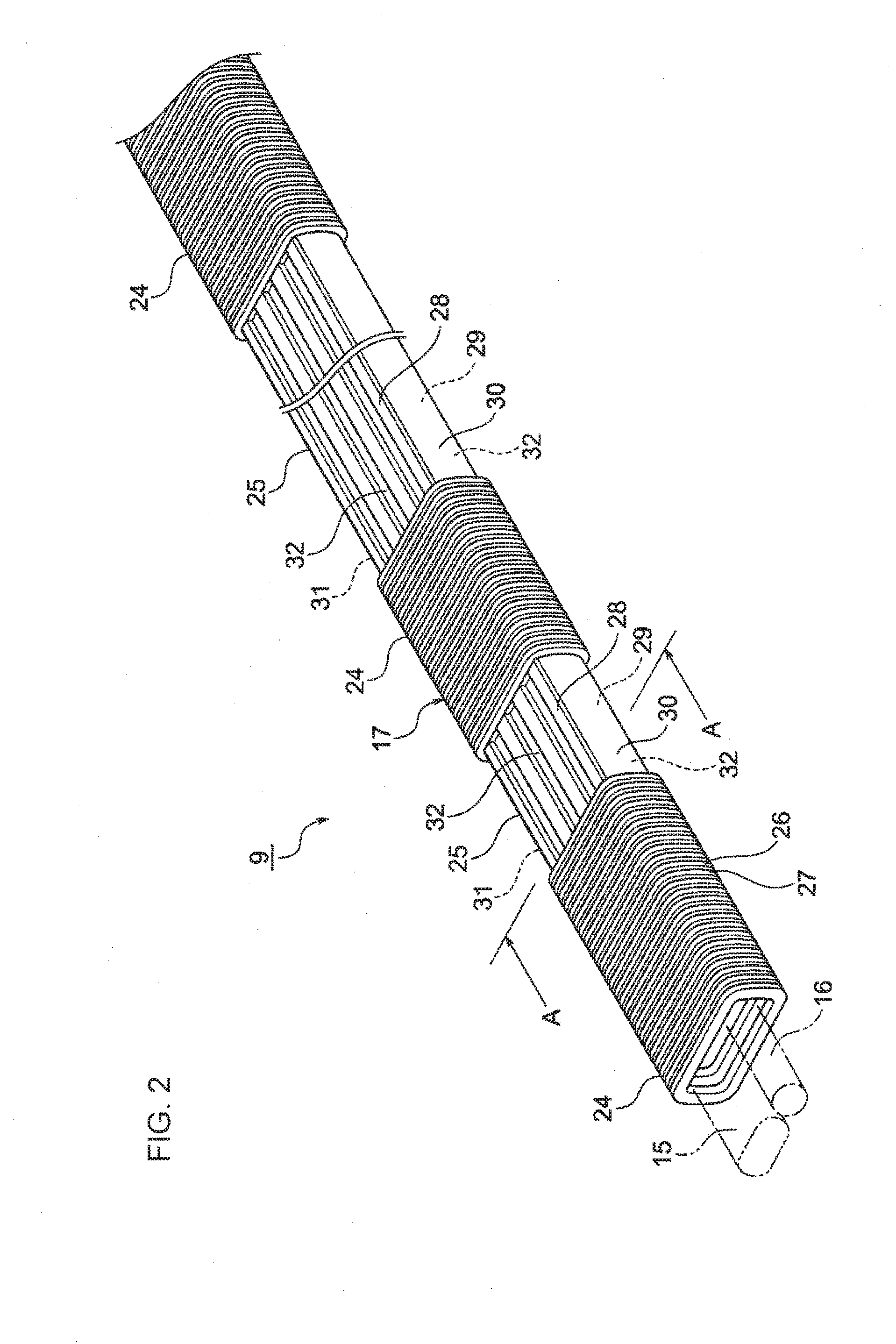
[0036]Hereinafter, Embodiment 1 will be described with reference to the accompanying drawings. FIG. 1 is a view schematically illustrating a routing state of a wire harness of the present invention. FIG. 2 is a perspective view of the wire harness, and FIG. 3 is a sectional view taken along line A-A in FIG. 2.
[0037]In the embodiment, the present invention is applied to a wire harness to be routed in a hybrid vehicle (which may be an electric vehicle or a typical automobile).
[0038]In FIG. 1, a hybrid vehicle 1 includes two power sources, that is, an engine 2 and a motor unit 3, and is driven by a combination of power from these power sources. Electric power is supplied from a battery (battery pack) 5 to the motor unit 3 via an inverter unit 4. In the embodiment, the engine 2, the motor unit 3, and the inverter unit 4 are mounted in an engine compartment 6 in the vicinity of the front wheels. The battery 5 is mounted in a vehicle rear portion 7 in the vicinity of the rear wheels (may ...
embodiment 2
[0076]Hereinafter, Embodiment 2 will be described with reference to the accompanying drawing. FIG. 4 is a perspective view of a wire harness as a modification example. The same reference signs are assigned to the same configuration members as in Embodiment 1, and detailed description thereof will be omitted.
[0077]In FIG. 4, similar to Embodiment 1, the exterior member 17 includes the flexible tubular portions 24 that can be flexed, and the straight tubular portions 25 having rigidity higher than that of the flexible tubular portions 24. The straight tubular portion 25 includes the one long-side wall portion 28; the other long-side wall portion 29; the one short-side wall portion 30; and the other short-side wall portion 31.
[0078]The plurality of concave portions 32 are formed in each of the one long-side wall portion 28 and the other long-side wall portion 29. In the embodiment, the plurality of concave portions 32 are partially disposed and formed. That is, the plurality of concave...
embodiment 3
[0080]Hereinafter, Embodiment 3 will be described with reference to the accompanying drawing. FIG. 5 is a sectional view of a wire harness as a modification example. The same reference signs are assigned to the same configuration members as in Embodiments 1 and 2, and detailed description thereof will be omitted.
[0081]In FIG. 5, similar to Embodiments 1 and 2, the exterior member 17 in Embodiment 3 includes the straight tubular portion 25. In the straight tubular portion 25, one concave portion 32 is formed in each of the one long-side wall portion 28 and the other long-side wall portion 29. Each of the concave portions 32 is formed to have a large width. In the embodiment, the straight tubular portion 25 is formed to a rectangular shape such that the section of the straight tubular portion 25 has a substantially H shape due to the concave portions 32.
[0082]In Embodiment 3, naturally, it is possible to prevent the occurrence of damage or the like by restricting the flexing of the ex...
PUM
 Abstract
Description
Claims
Application Information
 - R&D
- Intellectual Property
- Life Sciences
- Materials
- Tech Scout
- Unparalleled Data Quality
- Higher Quality Content
- 60% Fewer Hallucinations
Browse by: Latest US Patents, China's latest patents, Technical Efficacy Thesaurus, Application Domain, Technology Topic, Popular Technical Reports.
© 2025 PatSnap. All rights reserved.Legal|Privacy policy|Modern Slavery Act Transparency Statement|Sitemap|About US| Contact US: help@patsnap.com